


13369-1-0203 Page 35
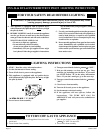
Important
1. The following service procedures are provided as a gen-
eral guide.
2. Meter readings between gas control and ignition module
must be taken within the trial for ignition period. Once the
ignition module locks out, the system must be reset by
setting the thermostat down for at least one minute before
continuing.
3. If any component does not function properly, make sure
it is correctly installed and wired before replacing it.
4. The ignition module cannot be repaired. If it malfunc-
tions, it must be replaced.
5. Only trained, experienced service technicians should ser-
vice intermittent pilot systems.
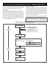
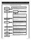
Perform the CHECKOUT steps on page 10 as the first step in
troubleshooting. Then check TROUBLESHOOTING
GUIDE to pinpoint the cause of the problem. If troubleshoot-
ing indicates an ignition problem, see Ignition System Checks
below to isolate and correct the problem.
Following troubleshooting, perform the CHECKOUT proce-
dure (page 10 ) again to be sure system is operating normally.
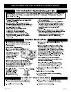
Ignition System Checks
Step 1: Check ignition cable.
Make sure:
A. Ignition cable does not touch any metal surfaces.
B. Ignition cable is no more than 36 inches long.
C. Connections to the ignition module and to the igniter-
sensor are clean and tight.
D. Ignition cable provides good electrical continuity.
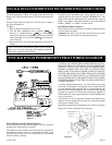
Step 2: Check ignition system grounding.
Nuisance shutdowns are often caused by a poor or
erratic ground.
A. A common ground, usually supplied by the pilot burner
bracket, is required for the module and the pilot burner/
igniter sensor.
• Check for good metal-to-metal contact between the
pilot burner bracket and the main burner.
• Check the ground lead from GND (BURNER) terminal
on the module to the pilot burner. Make sure connec-
tions are clean and tight. If the wire is damaged or
deteriorated, replace it with No. 14-18 gauge, mois-
ture-resistant, thermoplastic insulated wire with 105 C
(221 F) minimum rating.
• If flame rod or bracket are bent out of position, restore
to correct position.
• Replace pilot burner/igniter sensor if insulator is
cracked.
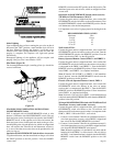
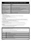
Step 3: Check spark ignition circuit. You will need a short
jumper wire made from ignition cable or other heavily
insulated wire.
A. Close the manual gas valve.
B. Disconnect the ignition cable at the SPARK terminal on
the module.
WARNING
When performing the following steps, do not touch
stripped end of jumper or SPARK terminal. The
ignition circuit generates 13,000 volts at 25 pf load and
electrical shock can result.
C. Energize the module and immediately touch one end of
the jumper firmly to the GND terminal on the module.
Move the free end of the jumper slowly toward the SPARK
terminal until a spark is established.
D. Pull the jumper slowly away from the terminal and note
the length of the gap when sparking stops. Check table
below.
ARC LENGTH ACTION
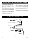
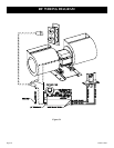
Step 4: Check pilot flame current.
A. Turn off furnace at thermostat.
B. Disconnect main valve wire from the TH or MV terminal
on the gas control.
C. Disconnect ground wire from GND (BURNER) terminal
at module.
D. Connect a meter (dc microamp scale) in series with the
ground lead.
• Disconnect ground lead from GND terminal on ignition
module.
• Connect the black (negative) meter lead to the ignition
module GND (BURNER) terminal.
• Connect the red (positive) meter lead to the free end of
the ground lead.
E. Set thermostat to call for heat. The spark will light the
pilot but the main burner will not light because the main
valve actuator is disconnected.
F. Read the meter. The flame sensor current must be steady
and at least 1.0 uA.
G. If the reading is less than the minimum or unsteady,
• Make sure pilot flame envelopes 3/8 to 1/2 inch of the
flame rod.
• If necessary, adjust pilot flame by turning the pilot
adjustment screw on the gas control clockwise to de-
crease or counterclockwise to increase pilot flame.
Following adjustment, always replace pilot adjustment
cover screw and tighten firmly to assure proper gas
control operation.
• Check for cracked ceramic insulator, which can cause
short to ground, and replace igniter-sensor if necessary.
• Make sure electrical connections are clean and tight.
Replace damaged wire with moisture-resistant No. 18
wire rated for continuous duty up to 105 C (221 F).
H. Remove meter and reconnect all wires. Return system to
normal operation before leaving job.
Check external fuse, if pro-
vided.
Verify power at module input
terminal.
Replace module if fuse and
power okay.
Voltage output is okay.
No arc or arc less than
1/8 inch.
Arc 1/8 inch or longer.