


13369-1-0203 Page 31
The intermittent pilot (120/24 volt system) is ON when the main
burner is ON. When the main burner is OFF the intermittent pilot
is OFF.
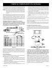
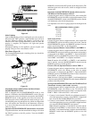
The pilot flame should envelop 3/8 to 1/2 inch (10 to 13mm) of
the tip of the flame rod.
To adjust:
1. Remove the pilot adjustment cover screw.
2. Turn the inner adjustment screw clockwise
to
decrease or counterclockwise
to increase pilot
flame. Pilot adjustment is shipped at full flow rate. Turn the
inner adjustment screw clockwise
if the inlet pres-
sure is too high.
3. Replace the cover screw after the adjustment to prevent gas
leakage.
Label all wires prior to disconnection when servicing controls.
Wiring errors can cause improper and dangerous operation.
Verify proper operation after servicing.
Figure 52
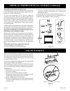
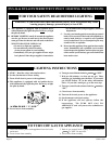
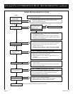
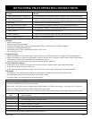
DVS-36 & DVS-42 INTERMITTENT PILOT OPERATING INSTRUCTIONS
Provided on the intermittent pilot wiring harness are two (2)
stripped and bare wires that are labeled THERMOSTAT. The
wires will be used for attachment of 24 volt thermostat, optional
FWS-1 wall switch or will attach into the receiver on an optional
FRBC-1, FRBTC-1 or FREC-1 remote control.
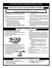
Installation of Remote Receiver
Place remote receiver on the floor of fireplace behind the louver
as far forward as possible.
Attention: The velcro loop and hook are not necessary in this
installation but can be used to secure remote receiver.
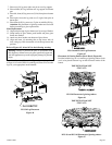
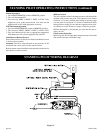
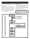
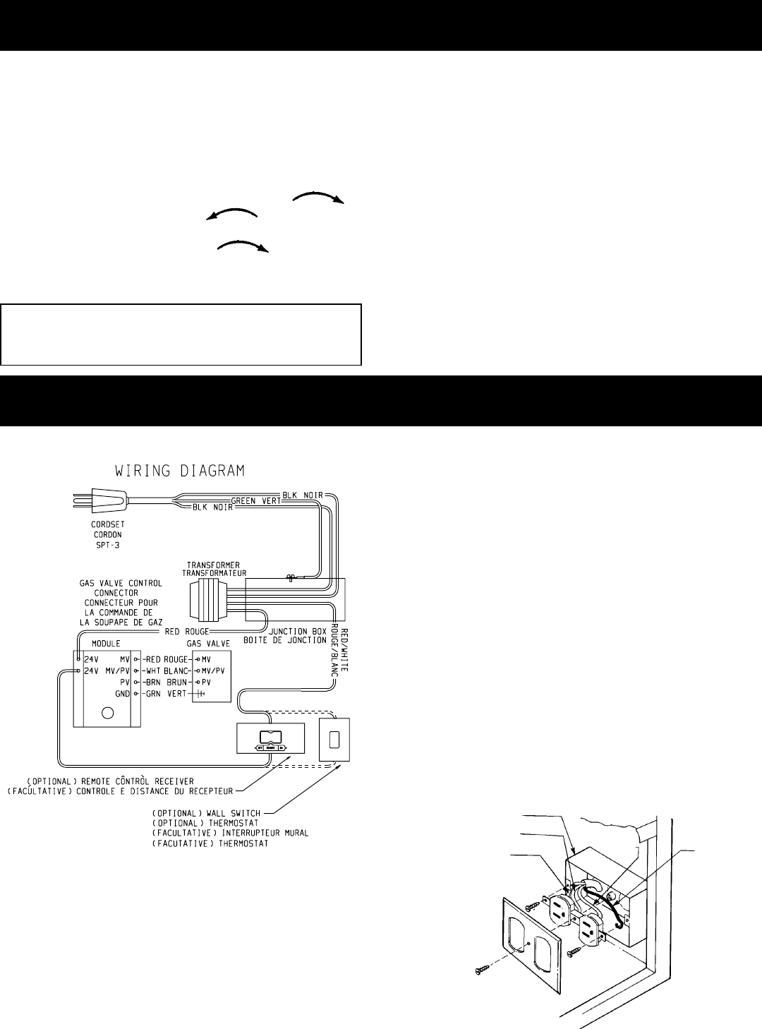
DVS-36 & DVS-42 INTERMITTENT PILOT WIRING DIAGRAM
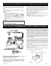
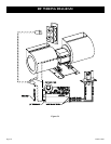
ELECTRICAL CONNECTION (Figure 53)
The DVS36/42IP with optional fan requires 120 VAC electrical
hookup to the electrical box (installed).
The appliance, when installed, must be electrically grounded in
accordance with local codes or, in the absence of local codes,
with the National Electrical Code, ANSI/NFPA 70, if an external
electrical source is utilized.
CAUTION: ALL WIRING SHOULD BE DONE BY A QUALI-
FIED ELECTRICIAN AND SHALL BE IN COMPLIANCE
WITH ALL LOCAL, CITY AND STATE BUILDING CODES.
BEFORE MAKING THE ELECTRICAL CONNECTION,
MAKE SURE THAT MAIN POWER SUPPLY IS DISCON-
NECTED. THE APPLIANCE, WHEN INSTALLED, MUST BE
ELECTRICALLY GROUNDED IN ACCORDANCE WITH
LOCAL CODES OR, IN THE ABSENCE OF LOCAL CODES,
WITH THE NATIONAL ELECTRICAL CODE ANSI/NFPA 70
(LATEST EDITION).
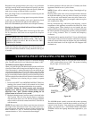
A factory installed electrical box is located on the lower right
hand side of the fireplace. Wiring must be fed to the electrical
box and attached to the receptacle that is provided. Remove the
knockout in the installed junction box to accept wiring into the
junction box. Install a UL listed cable clamp (not supplied) in
the knockout hole. Leave approximately 6" of wire in the junction
box for connection.
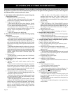
Attach black wire to one side of the receptacle and white wire to
opposite side of receptacle.The ground wire should be attached
to the green (neutral) screw.
Install the receptacle into the metal box with. Attach cover plate.
Plug cord set from transformer into receptacle.
JUNCTION BOX
NEUTRAL
BLACK
GROUND
WHITE
Figure 53