


13369-1-0203 Page 11
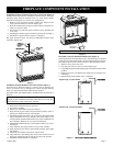
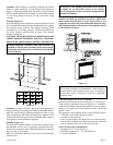
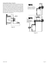
Attention: When fireplace is installed in optional full cabinet
mantel or corner mantel the (4) four nailing flanges shown in
Figure 11 will not be installed on the side of outer casing. The DVS
will be attached to the full cabinet mantel or corner mantel with the
(2) two nailing flanges located on the top of the outer casing
assembly.
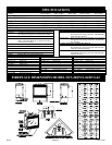
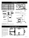
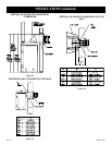
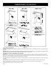
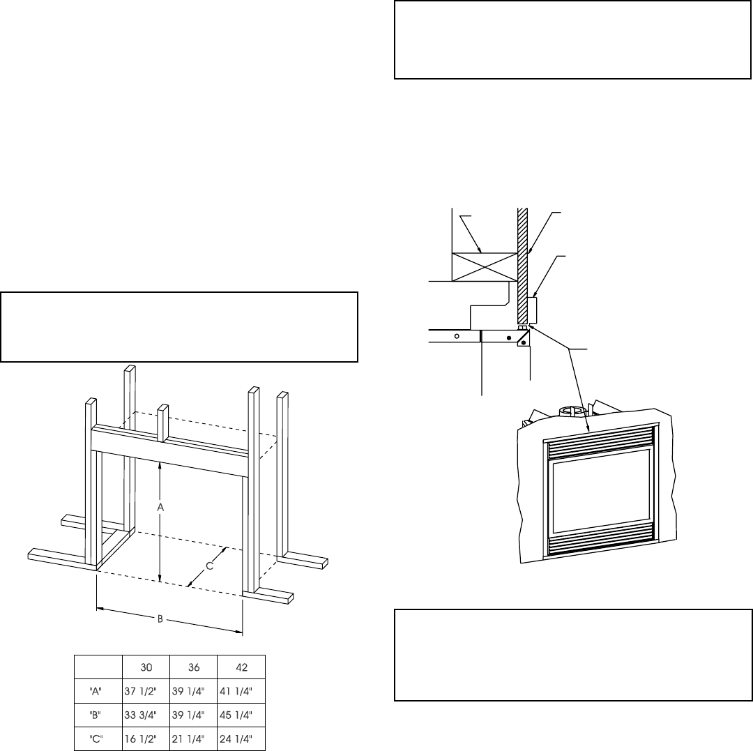
Framing (Figure 12)
Fireplace framing can be built before or after the fireplace is set in
place. Framing should be positioned to accommodate wall covering
and fireplace facing material. The fireplace framing should
constructed of 2 x 4 lumber or heavier. The framing headers may
rest on the fireplace standoffs. Refer to Figure 12 for framing
reference dimensions.
CAUTION: MEASURE FIREPLACE DIMENSIONS AND
VERIFY FRAMING METHODS, AND WALL COVERING
DETAILS BEFORE FRAMING CONSTRUCTION BEGINS.
Framing dimension A includes a three inch clearance for
standoffs on firebox. After installing firebox into framing,
the finished wall surface must cover the three inch opening
above the firebox.
Figure 12
Attention: If a base or mantel is not used and the appliance is
installed directly on carpeting, tile or other combustible material
other than wood flooring, it shall be installed on a metal or wood
panel extending the full width and depth of the appliance. The
vertical dimension in Figure 12 must be adjusted when a metal or
wood panel is placed beneath the appliance.
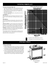
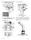
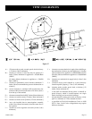
Finishing (Figure 13)
Finish the walls with the material of your choice. Figure 6 shows
the minimum vertical and corresponding maximum horizontal
dimensions of mantels or other combustible projections above the
top front edge of the fireplace.
Only non-combustible materials may be used to cover the black
fireplace front.
WARNING: When finishing the fireplace never obstruct
or modify the air inlet/outlet louvers in any manner.
Provide adequate clearances around air openings into the
combustion chamber.
Caution: If the joints between the finished wall and the
fireplace surround (top and sides) are sealed, a 300
°F mini-
mum sealant material must be used. These joints are not
required to be sealed. Only non-combustible material (using
300°F minimum adhesive if needed), can be applied as facing
to the fireplace surround.
FINISHED WALL
FINISHED WALL
2X4
2 X 4
HEADER
STAND OFF
STAND OFF
FRONT TRIMOR
FRONT TRIMOR
NON-COMBUSTIBLE MATERIAL
NON-COMBUSTIBLE MATERIAL
(INSTALLATION IS OPTIONAL)
(INSTALLATION IS OPTIONAL)
JOINT BETWEEN FINISHED
JOINT BETWEEN FINISHED
WALLAND UNIT SEALED
WALLAND UNIT SEALED
WITH 300°F, 149°C SEALANT
WITH 300°F, 149°C SEALANT
MATERIAL
Figure 13
Attention:
Cold climate installation recommendation: When installing
this unit against a non-insulated exterior wall, it is mandatory
that the outer walls be insulated to conform to applicable
insulation codes.
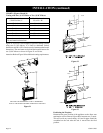
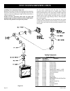
Vent Runs (Figures 14, 15, 16, 17 and 18)
In planning the installation for the fireplace, it is necessary to
install certain components before the appliance is completely
positioned and installed. These include the direct vent system, gas
piping for the appliance and the electrical wiring. (If the fan
option is used.)
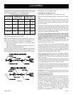
The appliance can be mounted on any of the following surfaces:
1. A flat, hard combustible (burnable) surface.
2. A raised wooden platform.
3. Four (4) corner supports. (Example: Four (4) concrete masonry
blocks.) These supports must be positioned so they contact all
four (4) perimeter edges on the bottom of the unit.
Three (3) basic types of installations
1. Straight out (4" - 8" wall thickness).
2. Extended straight out (8" - 36" wall thickness).
3. Vertical installations.