


Page 24 13369-1-0203
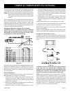
Before you begin: This unit is supplied with a set of five ceramic
fiber logs. Do not handle these logs with your bare hands! Al-
ways wear gloves to prevent skin irritation from ceramic fibers.
After handling logs, wash your hands gently with soap and water
to remove any traces of fibers.
Every burner is shipped with a shipping plate. This shipping plate
must be removed before log placement.
The positioning of the logs is critical to the safe and clean opera-
tion of this fireplace. Sooting and other problems may result if
the logs are not properly and firmly positioned in the fireplace.
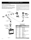
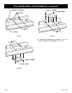
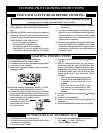
Glass Removal
1. Push up and outward to remove top louver.
2. Lower door assembly.
3. Release two door latches at bottom of firebox.
4. Grasp bottom of glass frame, lift glass frame upward in order
to release glass frame from lip on top of firebox.
5. Remove shipping plate from burner pan.
6. Place two (2) log grates onto two (2) left, front pins and two
(2) right, front pins on burner pan. Secure grates with two (2)
Tinnerman clips.
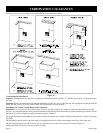
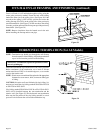
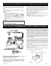
Reassembly and Resealing Vent Pipe System
Attach adapter pipe to vent cover in either the vertical or horizontal
position, replace horizontal and vertical pipe lengths, elbows and
horizontal or vertical termination kit.
All vent system components lock into place by sliding the
concentric pipe section with four (4) equally spaced interior
beads onto the appliance collar or previously installed component
end with four (4) equally spaced indented sections. When the
internal beads of each starting outer pipe line up, rotate pipe
section clockwise 90° (approximately 3 inches). The vent pipe is
now locked together.
Continue replacing components per the vent system configuration.
Be certain that each succeeding vent component is securely fitted
and locked into the preceding component in the vent system.
Reassembly and Resealing Gas Accumulation Relief System
(Relief Doors) and Combustion Chamber
Whenever the relief door is pivoted open by a delayed ignition in
the main burner, the relief door gaskets and combustion chamber
must be examined by a qualified service person for damage. All
damaged gaskets on the relief door and combustion chamber must
be replaced by a qualified service person. If damage occurs to the
combustion chamber, it must be replaced by a qualified service
person. Contact Empire Comfort Systems, Inc. for replacement
parts.
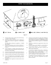
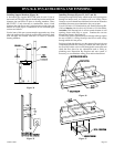
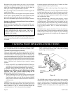
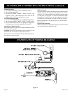
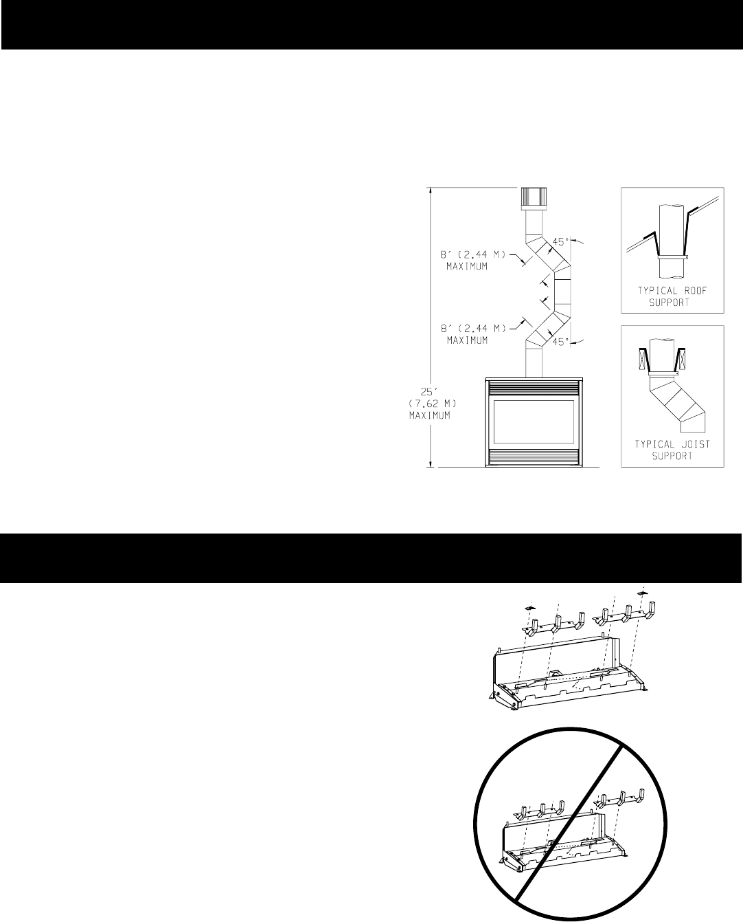
Vertical Through the Roof Applications (Figure 42)
Your Gas Fireplace has been approved for:
a) Vertical installations up to 25 feet in height.
b) Two sets of 45 degree elbow offsets within these vertical
installations. From 0 to a maximum of 8 ft. a vent pipe can be
used between elbows.
c) Wall straps must be used to support offset pipe every 4'.
This applications will require that you first determine the roof
pitch and use the appropriate venting components.
Figure 42
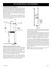
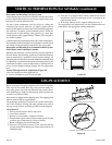
VERTICAL TERMINATION (For All Models) (continued)
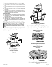
LOG PLACEMENT
Figure 43
CORRECT GRATE INSTALLATION FOR 42" LOG SETS
INCORRECT GRATE INSTALLATION FOR 42" LOG SETS