


Page 18 13369-1-0203
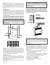
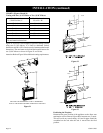
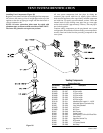
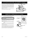
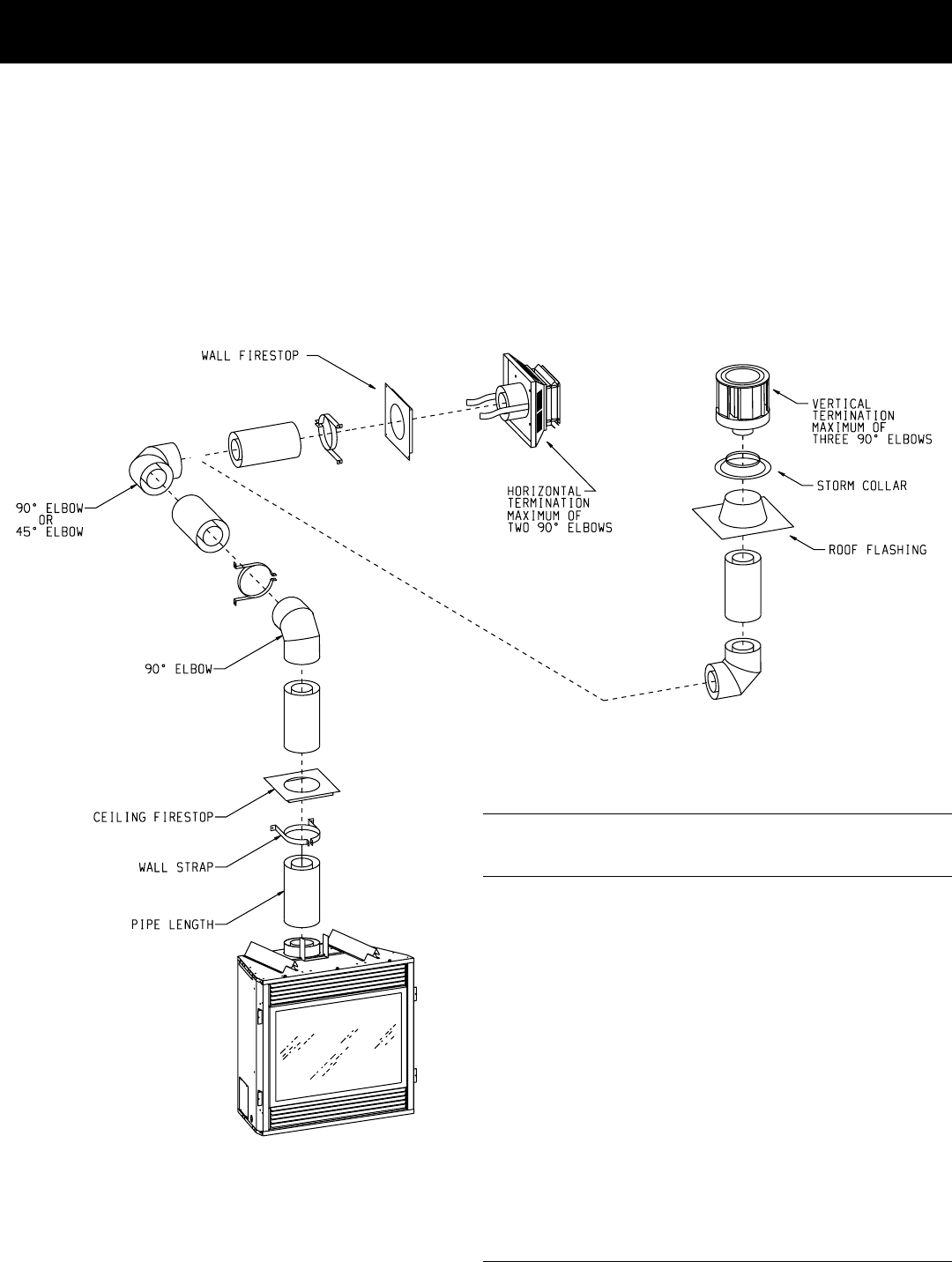
Installing Vent Components (Figure 28)
Begin the vent system installation by installing the first component,
90° elbow to the starting collars or straight pipe on the top of the
appliance, then the straight pipe length and then horizontal or
vertical termination kit.
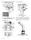
NOTE: All outer connection joints must be sealed with
aluminum tape or silicone sealant rated above 300°F/149°C.
The inner flue joints do not require any sealant.
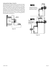
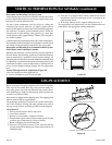
All vent system components lock into place by sliding the
concentric pipe section with four (4) equally spaced interior
beads onto the appliance collar or previously installed component
end with four (4) equally spaced indented sections. When the
internal beads of each starting outer pipe line up, rotate pipe
section clockwise 90° (approximately 3 inches). The vent pipe is
now locked together.
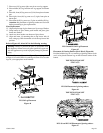
Continue adding components per the pre-planned vent system
configuration. Be certain that each succeeding vent component is
securely fitted and locked into the preceding component in the
vent system.
Figure 28
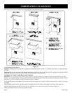
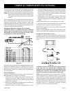
Venting Components
Simpson Dura-Vent
Part Number Part Number Description
DVS-30 DVS-36/DVS-42
SD-908B SD-1208 6" Pipe Length
SD-907B SD-1207 9" Pipe Length
SD-906B SD-1206 12" Pipe Length
SD-904B SD-1204 24" Pipe Length
SD-903B SD-1203 36" Pipe Length
SD-902B SD-1202 48" Pipe Length
SD-911B SD-1211 Adjustable Pipe Length 11 - 14 5/8"
SD-985 SD-1284 Horizontal Square Termination Cap
SD-950 SD-1250 Vinyl Siding Standoff
SD-945B SD-1245 45° Elbow
SD-990B SD-1290 90° Elbow
SD-947 SD-1249 Wall Firestop
SD-963 SD-1263 Ceiling Firestop
SD-943 SD-1243 Roof Flashing - 0/12 to 6/12 Roof Pitch
SD-953 SD-1253 Storm Collar
SD-991 SD-1291 High Wind Vertical Top
SD-981 SD-1281 36" Snorkel
SD-982 SD-1282 14" Firestop Snorkel
SD-988 SD-1288 Wall Strap
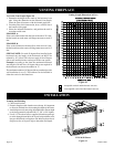
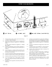
VENT SYSTEM IDENTIFICATION