


Page 14 13369-1-0203
Figure 22
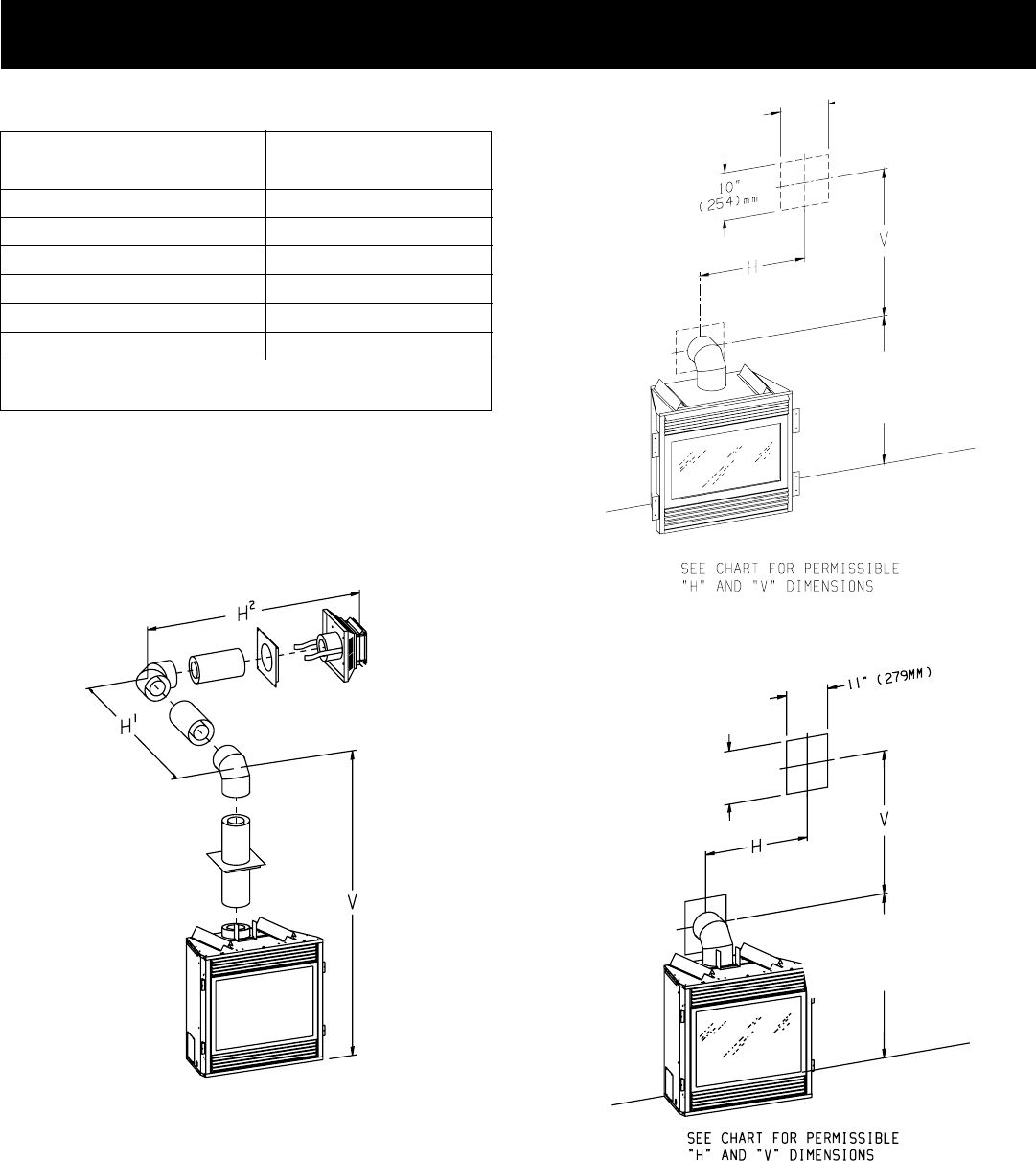
Figure 23
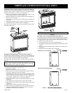
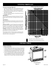
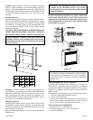
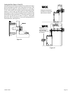
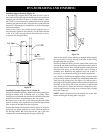
Positioning the Fireplace
Determine the exact position of the appliance so the direct vent
termination will be centered (if possible) between two (2) studs.
This will avoid any extra framing. All vent kit pipes should be
assembled on the unit after the unit is moved into the final
position.
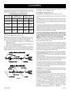
CHART 1 (Figures 20 and 21)
Venting with One (1) 90
° Elbow or Two (2) 90° Elbows
Total Vertical Total Horizontal
(With Fire Box) V H
1
or H
1
+ H
2
4.5' minimum 3' maximum
4.5' minimum 4' maximum
5' minimum 8' maximum
6' minimum 12' maximum
7' minimum 15' maximum
8' minimum 20' maximum
25' maximum vertical
20' maximum horizontal run
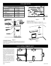
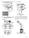
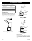
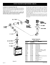
Figure 21 and Chart 1 list examples of possible venting systems
using two (2) 90° elbows. V is listed as minimum vertical
dimensions and H1 + H2 is listed as total of maximum horizontal
dimensions. The maximum vertical and horizontal distances for
two (2) 90° elbows as shown in Figure 21 are 20 feet.
Attention: Refer to Figure 10 for additional venting requirements.
SEE CHART FOR PERMISSIBLE "H"AND "V" DIMENSIONS
NOTE: H1 ANDH2 MUST BE ADDEDTOGETHER TO USE CHART
Figure 21
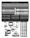
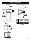
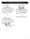
INSTALLATION (continued)
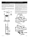
12 3/8"
10 3/8"
DVS-36 44 3/4" 114cm
DVS-42 46 3/4" 118cm
CENTER OF ELBOW
STRAIGHT OUT
DVS-30 37 5/8" ( 956mm)
CENTER OF ELBOW
STRAIGHT OUT