


www.desatech.com
112108-01C6
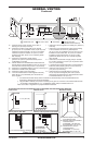
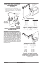
CLEARANCES
Minimum clearances to combustibles for the re-
place are as follows:
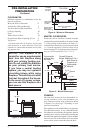
Back and Sides of Surround* 0"
Vent Surface (Side and Bottom) 1"
Top Vent Surface (Horizontal Run) 2"
Ceiling to Opening 36"
Floor 0"
Wall to Front of Glass 36"
Perpendicular Wall to Opening of Unit 2"
Top Spacer 0"
* For back and sides of replace, do not pack
with insulation or other materials. Zero inch
clearance to combustible materials are for fram-
ing purpose only.
-
-
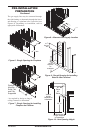
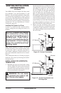
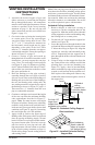
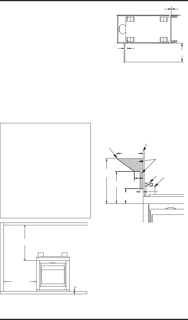
MANTEL CLEARANCES
Woodwork, such as wood trims, mantels and other
combustible materials should not be placed within
7" of the opening of this replace (see Figure 5).
Combustible material above projecting more than
1
1
/
2
" from the appliance’s front face must not be
placed less than 15" from the opening of the appli-
ance (ref. NFPA Standard 211 Sec. 7-3.3.3).
PRE-INSTALLATION
PREPARATION
Continued
0"
36"
2"
Wall In Front Of Glass
36" Min.
Perpendicular
Wall 2" Min.
From Opening
Right Side
Surround
(0" Min.)
Left Side
Surround
(0" Min.)
TOP VIEW
Figure 3 - Minimum Clearances
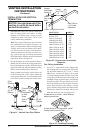
Figure 4 - Minimum Clearances
CEILING
WALL
36" Min.
36" Min.
0" Floor
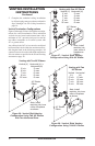
FRAMING
Once the nal location has been determined, ob-
serving clearances for the vent termination, you
may construct framing using dimensions shown
in Figures 6 to 10 on page 7 depending on your
particular installation
If the appliance is to be installed directly on carpeting,
tile (other than ceramic), or any combustible mate-
rial other than wood ooring, the appliance must be
installed upon a metal or wood panel extending the
full width and depth of the appliance. There are three
holes on each side of the bottom of the unit where
screws can be used to secure the unit to the oor.
Figure 5 - Mantel Clearances
21" Min.
15" Min.
12" Min.
4"
Min.
7" Min.
1
1
/
2
" Max.
UNIT
Spacer
2 x 4
Combustible
Material May
Be Used
Drywall (Gypsum
Board, Sheetrock, Etc.)
Safe Zone for
Projection of
Combustible
Material