


www.desatech.com
112108-01C 19
INSTALLATION
Continued
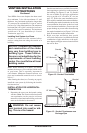
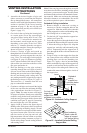
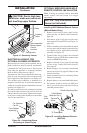
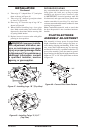
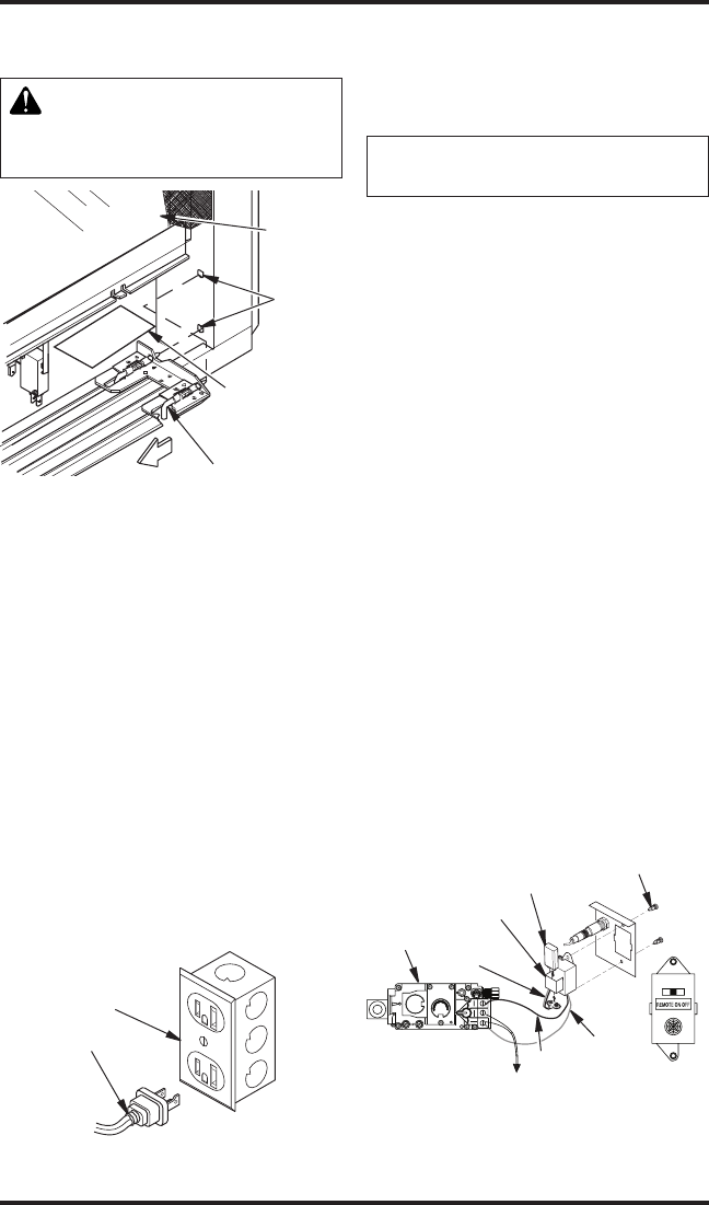
Figure 33 - Removing Louver
Glass
Locating
Holes
Spring Latch
Recommended
Blower Speed
Control
Location
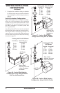
Before blower accessory can be operated, the ap-
pliance outlet box must be properly connected to
a standard 120 VAC power source. This must be
done when the appliance is originally installed.
Refer to Wiring Diagrams on page 31.
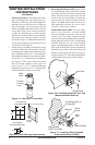
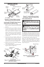
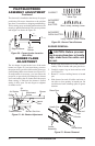
An outlet box with two receptacles has been sup-
plied for your convenience and is located on the
lower right side of the appliance (see Figure 34).
The variable speed controller is mounted on a
magnetic base and may be positioned anywhere
within an accessible distance behind the louvered
opening (see Figure 33).
You may test the blower for operation by turning
the control knob clockwise just until it clicks on
which is the full on position. Adjust the fan speed
to the lowest setting (this should be no more than
1/4 of a turn clockwise).
Figure 34 - Connecting Blower
Accessory to Power Supply
For Optional
Fan Kit
From Blower
Assembly
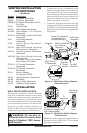
REMOTE CONTROL INSTALLATION
Note: If using an optional wireless hand-held
remote control, the wall switch is no longer
operational.
-
1. Remove lower louver access panel in re-
place (see step 1 of Wall Switch Installation,
page 18).
2. Disconnect wall switch wires from termi-
nals marked TH and TPTH (see Figure 32,
page 18).
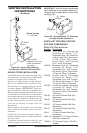
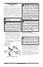
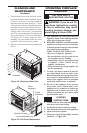
3. Slide 9-volt battery into clip on back of remote
receiver and connect battery terminals to bat-
tery. Mount receiver onto bracket with clips
provided (see Figure 35).
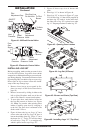
4. Connect white wire to control valve terminal
TH and red wire to TPTH. Move remote select
switch to REMOTE position.
5. Replace louvered access panel by following
reverse of step 1 under Wall Switch Installa-
tion, page 18.
6. Remove battery cover on back of hand-held
remote (see Figure 36, page 20). Remove and
discard sensor tag.
7. Attach terminal wires to 9-volt battery. Place
battery into housing.
8. Replace battery cover onto hand-held remote.
9. Set selector switch on receiver to OFF posi-
tion if you will be away from the unit for an
extended period of time.
FRONT
O
F
F
P
I
L
O
T
O
N
L
O
H
I
P
I
L
O
T
E A
16AI
7
TPTH TP TH
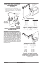
Figure 35 - Installing Remote Receiver
(HRC100)
Gas
Valve
To Thermopile
Receiver Clip
Terminal
Wires
Plastic Mounting Clips
9-Volt Battery
White
Red
-