


www.desatech.com
112108-01C14
VENTING INSTALLATION
INSTRUCTIONS
Continued
INSTALLATION FOR VERTICAL
TERMINATION
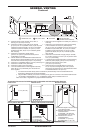
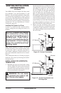
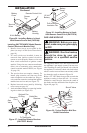
1. Determine the route your vertical venting will
take. If ceiling joists, roof rafters, or other
framing will obstruct the venting system,
consider an offset (see Figure 21) to avoid
cutting load bearing members.
Note: Pay special attention to these installa-
tion instructions for required clearances (air
space) to combustibles when passing through
ceilings, walls, roofs, enclosures, attic rafters,
etc. Do not pack air spaces with insulation.
Also note maximum vertical rise of the vent-
ing system and any maximum horizontal
offset limitations. Offsets must fall within the
parameters shown in Figure 22.
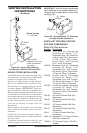
2. Set the replace in desired location. Drop a
plumb line down from the ceiling to the posi-
tion of the replace exit ue. Mark the center
point where the vent will penetrate the ceiling.
Drill a small locating hole at this point.
Drop a plumb line from the inside of the roof
to the locating hole in the ceiling. Mark the
center point where the vent will penetrate the
roof. Drill a small locating hole at this point.
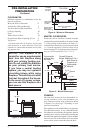
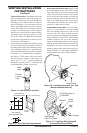
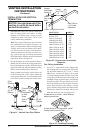
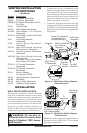
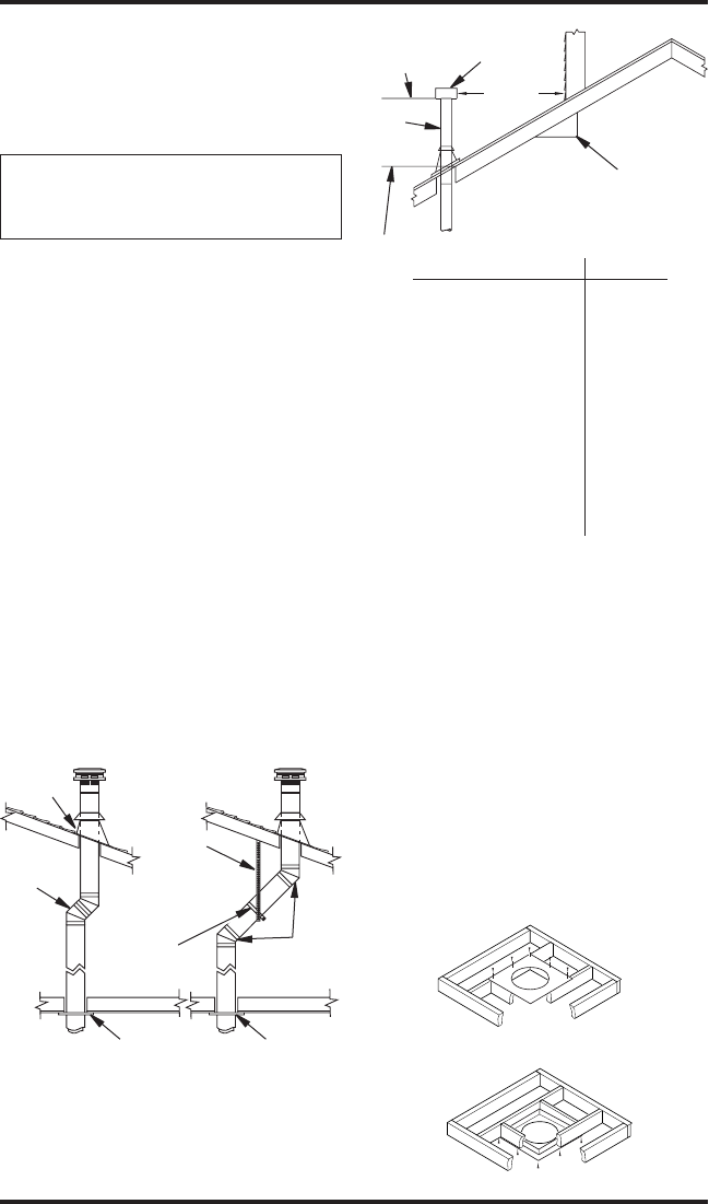
X
12
Roof Pitch is
x 12 Listed
Clearance
8'
Minimum
Listed
Vent Cap
Lowest
Discharge
Opening
Listed
Gas
Vent
H (Min.) Height from Roof
Figure 22 - Vertical Vent Termination
Clearance
Flat to 6/12 1.0'
6/12 to 7/12 1.25'
Over 7/12 to 8/12 1.5'
Over 8/12 to 9/12 2.0'
Over 9/12 to 10/12 2.5'
Over 10/12 to 11/12 3.25'
Over 11/12 to 12/12 4.0'
Over 12/12 to 14/12 5.0'
Over 14/12 to 16/12 6.0'
Over 16/12 to 18/12 7.0'
Over 18/12 to 20/12 7.5'
Over 20/12 to 21/12 8.0'
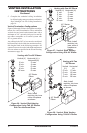
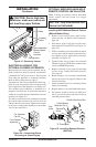
Figure 21 - Vertical Vent Pipe Offsets
Plumber’s
Tape
Connected
to Wall
Strap
Wall
Strap
Firestop
(2) 45°
Elbows
Firestop
(2) 45°
Elbows
Roof
Flashing
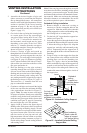
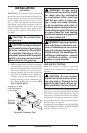
1. Cut a 10
3
/
4
" square hole in the ceiling using
the locating hole as a center point. The open-
ing should be framed to 10
3
/
4
"x10
3
/
4
" inside
dimensions, as shown in Figure 18 on page
13 using framing lumber the same size as the
ceiling joists. If the area above the ceiling is an
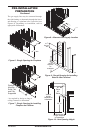
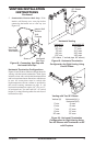
insulated ceiling or an attic space, nail restop
from the top side. This prevents loose insula-
tion from falling into the required clearance
space. If the area above the ceiling is a living
space, install restop below the framed hole.
The restop should be installed with no less
than three nails per side (see Figure 23).
Figure 23 - Installing Firestop
If area above is a living space, install
restop below framed hole.
If area above is an attic, install restop
above framed hole.