


www.desatech.com
112108-01C 21
INSTALLATION
Continued
IMPORTANT: The appliance and its individual
shutoff valve must be disconnected from the gas
supply piping system during any pressure testing
of that system at test pressures in excess of 1/2
psig. (3.5 kPa). The appliance must be isolated
from the gas supply piping system by closing its
individual equipment shutoff valve during any
pressure testing of the gas supply piping system
at test pressures equal to or less than 1/2 psig.
(3.5 kPa).
-
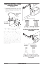
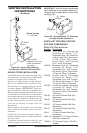
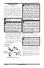
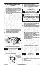
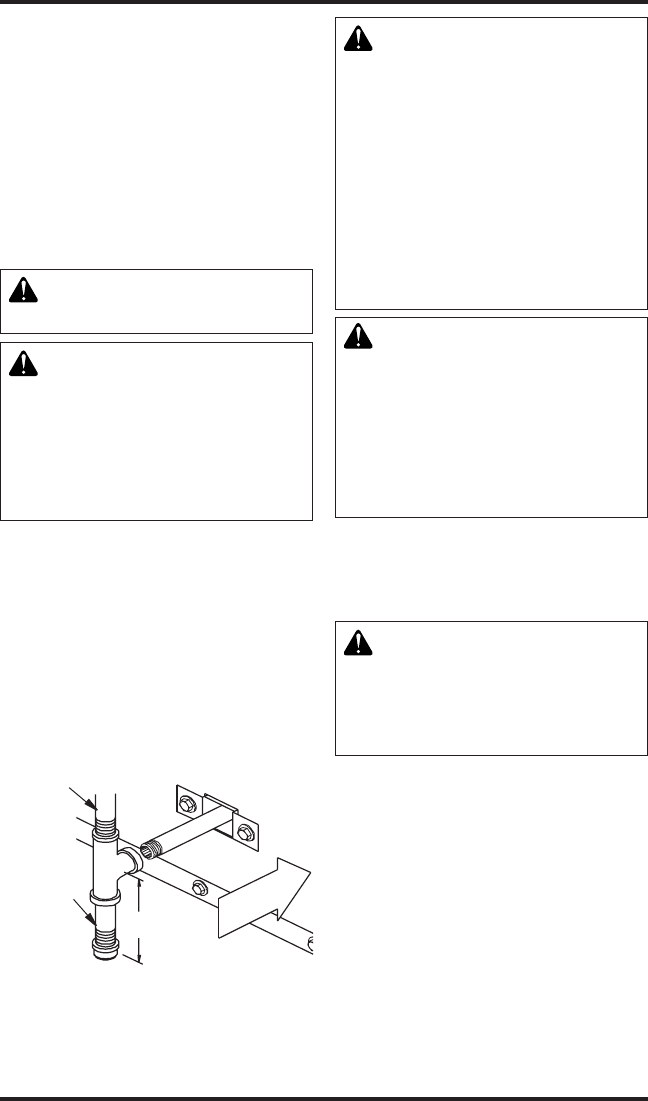
1. Install a sediment trap between the incoming
gas line and the gas control valve (see Figure
40). The sediment trap should extend down the
center of the pipe. Refer to your local codes.
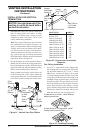
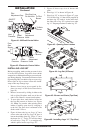
2. Prepare incoming gas line and check with
local codes regarding the use of teon tape.
Complete your gas line installation by con-
necting incoming gas line with exible gas
line. Secure tightly with a wrench, but DO
NOT OVERTIGHTEN.
3" Min.
Side W
all
Of
Appliance
Incoming 1/2" Gas
Line Permitted by
Local Codes
Figure 40 - Sediment Trap
Sediment
Trap (Not
Supplied)
for leaks after the installation
-
-
-
-
vice, or maintenance can cause
additional information, consult
Note: This section is intended as a guide for
qualied service technicians installing gas to the
appliance.
CAUTION: Do not connect
-
-
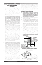
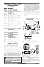
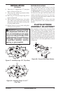
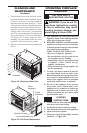
The millivolt system with a manual HI/LO ap-
plies only to the DVF36TCR, DVF36TCRP,
DVF36TCL and DVF36TCLP models. The gas
control valve is accessible from the lower control
compartment. Two pressure taps are provided on
the gas control valve for a pressure gauge connec-
tion (see Figure 41, page 22).
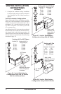
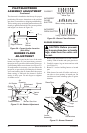
The electronic system applies to the DVF36TCRE,
DVF36TCRPE, DVF36TCLE and DVF36TCLPE
models (see Figure 42, page 22).