


www.desatech.com
112108-01C24
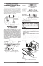
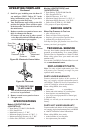
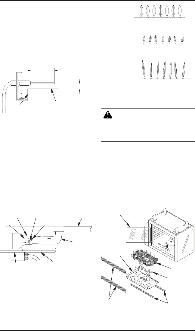
1/2"
(12.7 mm)
3/4"
(19 mm)
Edge of Burner
Top of
Burner
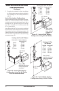
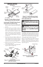
Figure 50 - Correct Ignitor Location
(Side View)
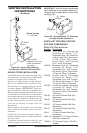
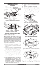
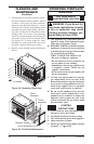
bURNER FLAME
ADjUSTMENT
The air shutter, located at the base of the main
burner (see Figure 51), has been factory preset to
the proper air-to-gas ratio which results in an even,
clean burning ame across burner (see Figure 52).
If readjustment is necessary, you can restore the
proper air-to-gas ratio by loosening the air shutter
screw and rotating the air shutter until the proper
ame setting is achieved (the shutter's normal
setting is fully open. Do not forget to retighten
air shutter screw.
Figure 52 - Burner Flame Patterns
Figure 51 - Air Shutter Adjustment
Air Shutter
Air
Opening
Burner
Venturi
Tube
Burner Gas Line
CORRECT
INCORRECT
CLOSE
SHUTTER
INCORRECT
OPEN SHUTTER
Short, Sharp, Blowing Flame
Long, Blue Flame with
Yellow Tips
Long, Uneven, Yellow Flame
Firebox Bottom
Adjustment
Screw
Orice
-
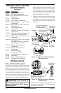
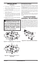
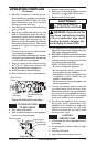
1. Remove top and bottom louvers and screen as-
sembly. Undo 4 latches and open glass door.
2. Carefully remove log set intact and set aside
(see Figure 53).
3. Remove 2 screws holding burner to hearth
pan.
4. Slide burner forward off orice and turn to
one side to clear opening in hearth pan. Be
careful not to bend or damage pilot or ignitor
element.
Figure 53 - Burner Removal
Glass Door
Refractories
Grate and
Logs
Burner
Hearth Pan
Louver
Assembly
The electrode is installed at the factory for proper
positioning. However, alterations to the position
may have occurred due to shipping and handling.
These settings may need adjustment and must be
done by a qualied technician. The correct position
and height is as shown in Figure 50.
PILOT/ELECTRODE
ASSEMbLy ADjUSTMENT
Continued