


www.desatech.com
112108-01C18
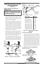
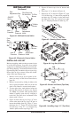
E58-45 45° Elbow, Galvanized
E58-90 90° Elbow, Galvanized
FSE58-45 45° Starter Elbow (Dura Vent to
FMI Pipe)
FP-58 Firestop Plate
WF-58 Wall Firestop, Galvanized
RF-58-6 Roof Flashing - 0 to 6/12 Pitch,
Galvanized
RF-58-12 Roof Flashing - 6/12 to 12/12 Pitch,
Galvanized
S-58 Vinyl Siding Standoff,
Galvanized
VT-58 Vertical Round Termination,
Galvanized
HHT-58 High WInd Round Horizontal
Termination Kit, Galvanized
HTS-58 Square Horizontal Termination,
Galvanized
HHTK-58 High Wind Round Horizontal
Termination Kit
(Includes Round Termination,
Wall Firestop, 45° Elbow)
ST-58-14 14" Snorkel Termination,
Galvanized
ST-58-36 36" Snorkel Termination,
Galvanized
SF-58 Stucco Flashing -
For use with HTS-58
VR-58 Vertical Restrictor, Galvanized
WS-58 Wall Strap
SC-58 Storm Collar, Galvanized
CS-58 Cathedral Ceiling Support
VENTING INSTALLATION
INSTRUCTIONS
Continued
INSTALLATION
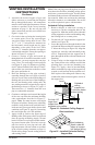
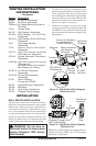
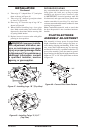
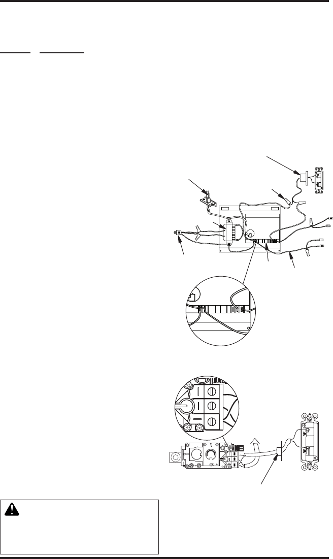
WALL SWITCH INSTALLATION
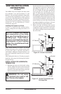
The electronic version uses a 24 VAC current sup-
plied from a transformer mounted on the ignition
module and is prewired for easy connection to a
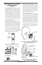
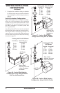
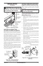
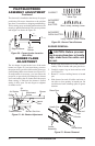
wall switch (see Figure 31). The millivolt version
uses a self generated millivolt current that allows
you to activate the gas control valve directly with-
out the use of normal household electricity (see
Figure 32). Both versions are supplied with a wall
switch kit for ready connection and mounting.
WARNING: Do not wire re-
-
V1
SW
SI
TS
IND
V2
L1
D
N
G
P.
Figure 31 - Wall Switch Wiring Diagram,
Electronic Units
Route 24V (Supplied)
Through Electrical
Conduit Bushing
Electrode
Transformer
Plug 120V AC
To Receptacle
18 AWG
Red Wire
Wall Switch
(Supplied)
Make Connections
with Wirenuts
(Supplied)
Ignition
Control
Module
(Back
View)
V1
SW
SI
TS
IND
V2
L1
D
N
G
P.
Figure 32 - Wall Switch Wiring Diagram,
Millivolt Units
Note: If any of the original wire supplied must be
replaced, use type 18 AWG-105° C (25 feet length
maximum) or equivalent.
O
F
F
P
I
L
O
T
O
N
L
O
H
I
P
I
L
O
T
E A
16AI
7
TPTH TP TH
Wall Switch
(Supplied)
Route Millivolt Wires
(Supplied) Through Gas
Line Conduit Sleeve
To
Thermopile
(Back
View)
O
F
F
P
I
L
O
T
O
N
L
O
H
I
P
I
L
O
T
E A
16AI
7
TPTH TP TH
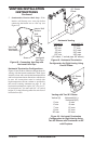
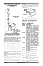
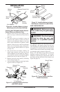
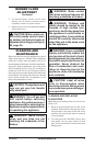
1. To remove the louvers, simultaneously pull
both top end spring latches towards the center
of the appliance until they are disengaged
from locating holes. Repeat for bottom spring
latches and pull louvers outward. Reverse the
procedure to install louvers back onto the ap-
pliance (see Figure 33, page 19).
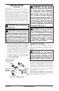
2. Connect the 18 gauge wires from wall switch
to the gas control valve terminals marked TH
and TPTH or to the ignition module using the
pigtails and wire nut connectors supplied with
the appliance.