


www.desatech.com
112108-01C 15
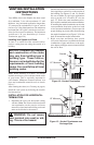
VENTING INSTALLATION
INSTRUCTIONS
Continued
2.
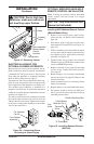
Assemble the desired lengths of pipe and
elbows necessary to reach from the replace
ue up through the restop. All connections
must be sealed with high temperature silicone
sealant as specied in the second warning
statement on page 11. Be sure all pipe and
elbow connections are fully twist-locked (see
Figure 14, page 12 ).
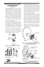
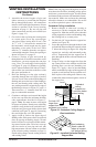
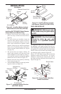
3. Cut a hole in the roof using the locating hole
as a center point. (Cover any exposed open
vent pipes before cutting hole in roof.) The
10
3
/
4
" x 10
3
/
4
" hole must be measured on
the horizontal; actual length may be larger
depending on the pitch of the roof. There
must be a 1" clearance from the vent pipe to
combustible materials. Frame the opening as
shown in Figure 15 on page 12.
4. Connect a section of pipe and extend up
through the hole. If an offset is needed to avoid
obstructions, you must support the vent pipe
every 3 feet. Use wall straps for this purpose
(see Figure 21, page 14). Whenever possible,
use 45° elbows instead of 90° elbows. The 45°
elbow offers less restriction to the ow of the
ue gases and intake air.
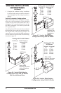
5. Place the ashing over the pipe section(s)
extending through the roof. Apply a bead of
silicone or roof sealer to the bottom ange of
ashing and secure the base of the ashing to
the roof and framing with roong nails. Be
sure roong material overlaps the top edge of
the ashing as shown in Figure 21, page 14.
There must be a 1" clearance from the vent
pipe to combustible materials.
6. Continue to add pipe sections until the height
of the vent cap meets the minimum building
code requirements described in Figure 11,
page 9. Note: You must increase vent height
for steep roof pitches. Nearby trees, adjoining
rooines, steep pitched roofs, and other simi-
lar factors may cause poor draft or down-draft
condition (see Figure 22, page 14). Increasing
the vent height may solve this problem.
7. Apply a bead of sealer to the upper edge of
ashing collar. Slide storm collar over pipe and
down to top edge of ashing. Apply a second
bead of silicone or roof sealer around remain-
ing seam of storm collar. Twist-lock vent cap
onto last section of vent pipe and seal with
high temperature silicone sealant as specied
in the second warning statement on page 10.
Finish sealing ange around roong material
with roong sealer.
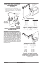
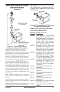
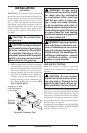
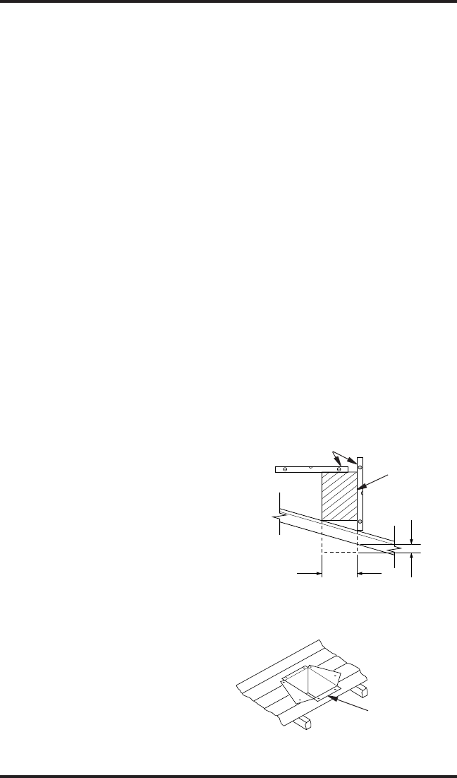
Figure 24 - Cathedral Ceiling Support
Box Installation
Cut hole 1/8"
larger than
support box when
projected onto rooine
2" minimum below
nished ceiling
Cathedral
ceiling
support box
Level
Note: If the vent pipe passes through any occupied
areas above the rst oor, including storage spaces
and closets, you must enclose pipe. You may frame
and sheetrock the enclosure with standard construc-
tion material. Make sure and meet the minimum
allowable clearances to combustibles. Do not ll
any of the required air spaces with insulation.
1. Remove shingles or other roof covering as
necessary to cut the rectangular hole for the
support box. Mark the outline of the cathedral
ceiling support box on the roof sheathing using
the locating hole as a center point.
2. Cut the hole 1/8" larger than the support box
outline (see Figure 24).
3. Lower the support box through the hole in the
roof until the bottom of the box extends at least
2" below the ceiling (see Figure 24). Align the
support box vertically and horizontally using
a level. Temporarily tack the support box in
place through the inside walls and into the roof
sheathing.
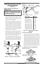
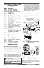
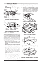
4. Using tin snips, cut the support box from the
top corners down to the rooine and fold the
resulting aps over the roof sheathing (see
Figure 25). Apply a bead of non-hardening
mastic around the top edges of the support box
to make a seal between the box and the roof.
Nail in place with roong nails. Remove any
combustible material that might be inside of
the support box.
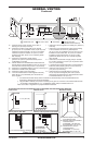
Non-hardening
Mastic under all
edges of support
box before nailing
Figure 25 - Installed Cathedral Ceiling
Support Box