


www.desatech.com
115254-01A
18
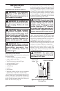
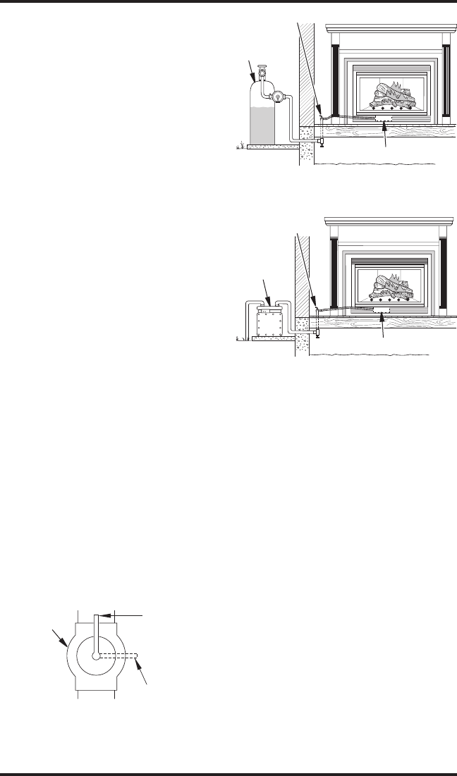
Propane/LP
Supply Tank
PRESSURE TESTING GAS SUPPLY
PIPING SYSTEM
Test Pressures In Excess Of 1/2 PSIG
(3.5 kPa)
1. Disconnect appliance with its appliance main
gas valve (control valve) and equipment
shutoff valve from gas supply piping system.
Pressures in excess of 1/2 psig will damage
heater regulator.
2. Cap off open end of gas pipe where equipment
shutoff valve was connected.
3. Pressurize supply piping system by either
opening propane/LP supply tank valve for
propane/LP gas or opening main gas valve
located on or near gas meter for natural gas
or using compressed air.
4. Check all joints of gas supply piping system.
Apply noncorrosive leak detection fluid to all
joints. Bubbles forming show a leak.
5. Correct all leaks at once.
6. Reconnect heater and equipment shutoff
valve to gas supply. Check reconnected fit
-
tings for leaks.
Test Pressures Equal To or Less Than
1/2 PSIG (3.5 kPa)
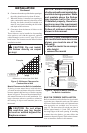
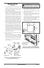
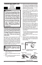
1. Close equipment shutoff valve (see Figure 23).
2. Pressurize supply piping system by either
opening propane/LP supply tank valve for
propane/LP gas or opening main gas valve
located on or near gas meter for natural gas
or using compressed air.
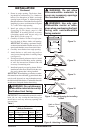
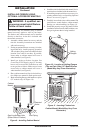
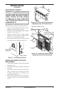
3. Check all joints from gas meter to equipment
shutoff valve for natural gas or propane/LP
supply to equipment shutoff valve for propane/
LP (see Figure 24 and 25). Apply noncorrosive
leak detection fluid to all joints. Bubbles form
-
ing show a leak.
4. Correct all leaks at once.
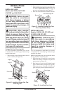
Open
Closed
Equipment
Shutoff Valve
Figure 23 - Equipment Shutoff Valve
INSTALLATION
Continued
Equipment
Shutoff Valve
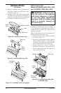
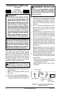
Figure 25 - Checking Gas Joints
(Natural Gas Only)
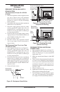
Figure 24 - Checking Gas Joints
(Propane/LP Gas Only)
Equipment Shutoff Valve
Gas
Meter
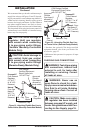
Control Valve Location
Control Valve Location
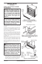
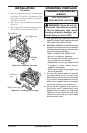
PRESSURE TESTING HEATER GAS
CONNECTIONS
1. Open equipment shutoff valve (see Figure 23).
2. Open main gas valve located on or near gas
meter for natural gas or open propane/LP
supply tank valve.
3. Make sure control knob of heater is in the OFF
position.
4. Check all joints from equipment shutoff valve
to control valve (Manually-Controlled Mod
-
els) or to gas control (Remote-Ready Models)
(see Figures 24 and 25). Apply noncorrosive
leak detection fluid to all joints. Bubbles form
-
ing show a leak.
5. Correct all leaks at once.
6. Light heater (see Operating Fireplace, page 21).
Check all other internal joints for leaks.
7. Turn off heater (see To Turn Off Gas to Appli
-
ance, page 23 for Manually-Controlled Mod-
els or page 25 for Remote-Ready Models).