


www.desatech.com
115254-01A 11
INSTALLATION
Continued
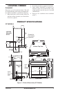
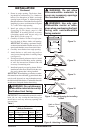
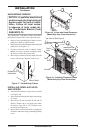
1. Frame in rough opening. The firebox fram-
ing should be constructed of 2 x 4 lumber or
heavier. Use dimensions in Table 1 and rough
opening layout in Figure 7a. Adjust framing so
that firebox flushes with finished wall surface. If
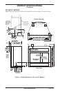
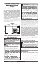
installing in a corner, use dimensions in Figures
7b, 7c and 7d for rough opening.
2. Install gas piping to firebox location (see
Connecting to Gas Supply, page 16.) IM
-
PORTANT:
If installing blower accessory
(circulating models with louvers only), see
Hard-Wiring Firebox,
page 15.
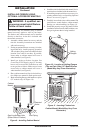
3. Carefully set firebox in front of rough open
-
ing with back of firebox inside wall opening.
IMPORTANT: If installing a perimeter trim kit,
see instructions included with trim accessory. You
must install shoulder screws from trim kit now.
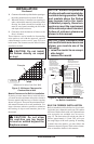
4. Carefully insert firebox into rough opening.
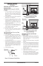
5. Attach firebox to wall studs using nails or
wood screws through holes in nailing flange
(see Figure 8).
6. If using an optional perimeter trim kit, install
the trim after final finishing and/or painting
of wall. See instructions included with trim
accessory for attaching trim.
7. Install and properly test gas log heater. Follow
installation instructions included with the vent-
free gas log heater that is being installed.
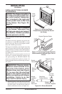
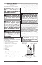
IMPORTANT:
When finishing your firebox, combus-
tible materials such as wall board, gypsum board, sheet
rock, drywall, plywood, etc. may be butted up next to
the sides and top of the firebox. Combustible materials
should never overlap the firebox front facing.
WARNING: Do not allow any
combustible materials to overlap
the firebox front facing.
IMPORTANT: Noncombustible materials such as
brick, tile, etc. may overlap the front facing, but
should never cover any necessary openings like
louvered slots.
Front Width Depth
Model (Inside to Inside) Height (Min.)
32" 34
7
/
8
" 36
3
/
4
" 16
1
/
4
"
36" 41
1
/
2
" 40
1
/
2
" 20
3
/
4
"
42" 48
5
/
8
" 44
1
/
2
" 22
5
/
8
"
Rough Opening Dimensions for
Built-in Installation
Table 1
Figure 7 - Rough Opening for Installing
in Wall
Depth
(Minimum)
Widt
h
(Inside to Inside)
Height
Figure 7a
37"
41
1
/
2
"
5
2
11
/
32
"
74"
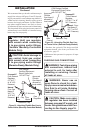
TOP
VIEW
FOR 36"
MODELS
Figure 7c
30"
34
7
/
8
"
42
7
/
16
"
60"
TOP VIEW
FOR 32"
MODELS
43"
48
5
/8"
6
0
13
/
1
6
"
86"
TOP
VIEW
FOR 42"
MODELS
Figure 7d
WARNING: Do not allow
noncombustible materials to
cover any necessary openings
like louvered slots.
WARNING: Use only non-
combustible mortar or adhe-
sives when overlapping the front
facing with noncombustible
facing material.
Figure 7b
Figure 8 - Attaching Firebox to Wall Studs
Nailing
Flanges
Nails or Wood
Screws