


www.desatech.com
115254-01A
14
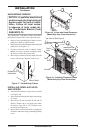
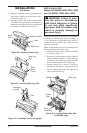
2. Attach green ground wire from power cord
to blower housing using screw provided (see
Figure 14, page 13). Tighten screws securely
with a phillips screwdriver.
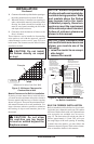
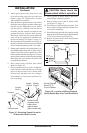
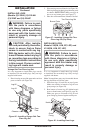
3. Place the blower against the lower rear wall of
the firebox outer wrapper with the exhaust port
directed upward. Depending on your model,
you may have to carefully route the blower
assembly past the controls and brackets and
position the blower inside the back opening.
The blower will be held in position against the
back wall by the magnets incorporated onto
the blower housing (see Figure 14, page 13).
4. Be certain that all wire terminals are securely at
-
tached to terminals on blower motor and that the
screw retaining the green ground wire is tight.
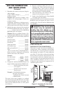
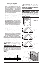
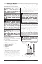
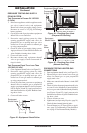
5. Mount speed control box by placing plastic con
-
trol shaft through bottom hole on speed control
bracket. Top screw head on control box will fit
inside top hole on bracket (see Figure 15). Secure
speed control to bracket with lock nut by pushing
and turning lock nut with pliers clockwise until
it is tight against bracket.
6. Place control knob, provided, onto control
shaft (see Figure 15).
7. Check to make sure power cord is completely
clear of blower wheel and there are no foreign
objects in blower wheel. Also, double check
all wire leads and make sure wire routing is
not pinched or in a precarious position. Cor
-
rect accordingly.
INSTALLATION
Continued
CAUTION: Never touch the
blower wheel while in operation.
8. Turn on power to duplex outlet if previously
turned off per warning on page 13.
9. Plug in blower power cord to duplex outlet
(see Figure 15, page 13).
10. Turn blower on and check for operation. Turn
blower off by turning knob fully counterclock
-
wise before continuing.
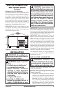
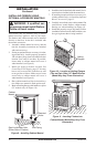
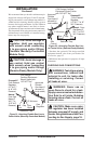
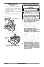
11. Peel off backing paper and stick supplied wiring
diagram decal on firebox bottom approximately
12" in from of blower (see Figure 16).
12. Replace all panels and/or brick bottom panel
if previously removed.
Figure 15 - Attaching Speed Control to
Firebox with Panel Louvers
Figure 16 - Location of Wiring Diagram
Decal (Model May Vary From Illustration)
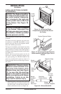
Wiring Diagram
Decal 12" in
Front of Blower
Red
Va
riable
Fan Switch
Fan Switch
(N.O.)
Green
White
On
11
0/115
V.
A.C.
Blower
Motor
Black
Off
1
2
Black
Blue
(BKT Model
Only)
Control
Shaft
Locknut
Control Knob
Speed
Control
Blower
Plug-In
Duplex Outlet
(Located under
firebox floor
against lower
right outside wall)