


www.desatech.com
56131-F 15
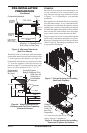
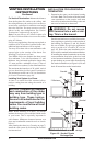
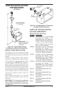
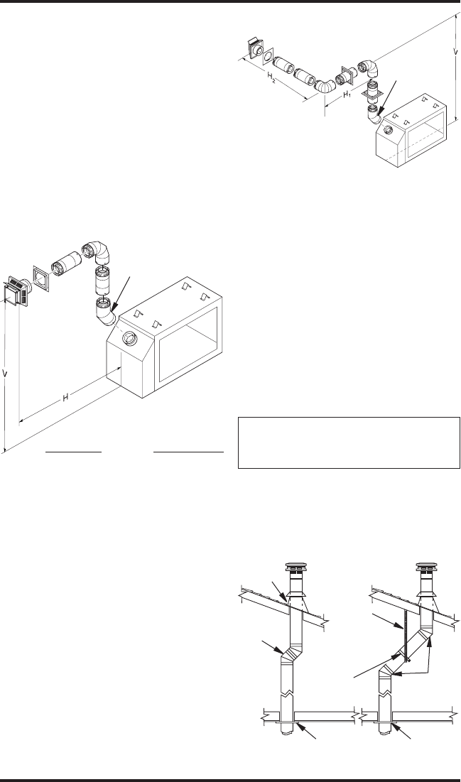
Figures 22 and 23 show different congurations for
venting with horizontal termination. Each gure
includes a chart with vertical minimum/maximum
and horizontal maximum dimensions which must
be met. All connections must be sealed with
high temperature silicone sealant as specied in
the second warning statement on page 11. All
horizontal terminations require 1/4" rise per 12"
of horizontal run. You must add 1/4" of vertical
height (V) in the following tables for each foot of
horizontal run (H).
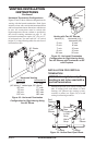
Figure 22 - Horizontal Termination
Conguration for Rigid Venting Using
One 90° Elbow
Vertical (V) Horizontal (H)
49.5" min. 17" max.
(45° elbow, 1' vertical pipe, 90° elbow)
60" min. 77" max.
72" min. 101" max.
84" min. 125" max.
132" min. 149" max.
VENTING INSTALLATION
INSTRUCTIONS
Continued
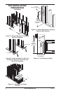
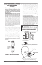
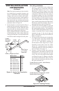
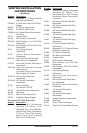
Vertical (V) Horizontal (H1) +
Horizontal (H2)
5' min. 4' max.
6' min. 8' max.
7' min. 10' max.
8' min. 15' max.
20' max. 20' max.
Figure 23 - Horizontal Termination
Conguration for Rigid Venting Using
Two 90° Elbows with Termination at 90°
with Fireplace
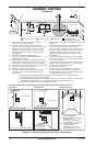
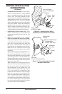
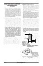
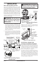
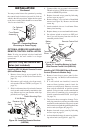
INSTALLATION FOR VERTICAL
TERMINATION
1. Determine the route your vertical venting will
take. If ceiling joists, roof rafters, or other
framing will obstruct the venting system,
consider an offset (see Figure 24) to avoid
cutting load bearing members.
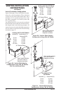
Figure 24 - Vertical Cent Pipe Offsets
Plumber’s
Tape
Connected
to Wall
Strap
Wall
Strap
Firestop
(2) 45°
Elbows
Firestop
(2) 45°
Elbows
Roof
Flashing
45° Starter
Elbow
45° Starter
Elbow