


www.desatech.com
56131-F 17
VENTING INSTALLATION
INSTRUCTIONS
Continued
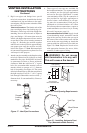
5. Place the ashing over the pipe section(s)
extending through the roof. Apply a bead of
silicone or roof sealer to the bottom ange of
ashing and secure the base of the ashing to
the roof and framing with roong nails. Be
sure roong material overlaps the top edge of
the ashing as shown in Figure 24, page 15.
There must be a 1" clearance from the vent
pipe to combustible materials.
6. Continue to add pipe sections until the height
of the vent cap meets the minimum building
code requirements described in Figure 14,
page 10. Note: You must increase vent height
for steep roof pitches. Nearby trees, adjoining
rooines, steep pitched roofs, and other simi-
lar factors may cause poor draft or down-draft
condition (see Figure 24, page 15). Increasing
the vent height may solve this problem.
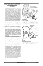
7. Apply a bead of sealer to the upper edge of
ashing collar. Slide storm collar over pipe
and down to top edge of ashing. Apply a
second bead of silicone or roof sealer around
remaining seam of storm collar. Twist-lock
vent cap onto last section of vent pipe and
seal with high temperature silicone sealant as
specied in the second warning statement on
page 11. Finish sealing ange around roong
material with roong sealer.
Note: If the vent pipe passes through any occupied
areas above the rst oor, including storage spaces
and closets, you must enclose pipe. You may frame
and sheetrock the enclosure with standard construc-
tion material. Make sure and meet the minimum
allowable clearances to combustibles. Do not ll
any of the required air spaces with insulation.
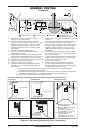
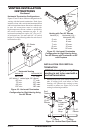
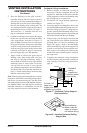
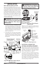
Figure 27 - Cathedral Ceiling Support
Box Installation
Cut hole 1/8"
larger than
support box when
projected onto rooine
2" minimum below
nished ceiling
Cathedral
ceiling
support box
Level
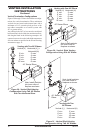
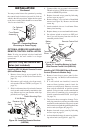
1. Remove shingles or other roof covering as
necessary to cut the rectangular hole for the
support box. Mark the outline of the cathedral
ceiling support box on the roof sheathing using
the locating hole as a center point.
2. Cut the hole 1/8" larger than the support box
outline (see Figure 27).
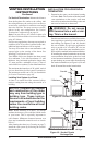
3.
Lower the support box through the hole in the
roof until the bottom of the box extends at least 2"
below the ceiling (see Figure 27). Align the sup-
port box vertically and horizontally using a level.
Temporarily tack the support box in place through
the inside walls and into the roof sheathing.
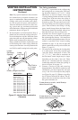
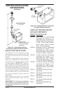
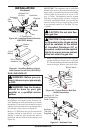
4. Using tin snips, cut the support box from the
top corners down to the rooine and fold the
resulting aps over the roof sheathing (see
Figure 28). Apply a bead of non-hardening
mastic around the top edges of the support box
to make a seal between the box and the roof.
Nail in place with roong nails. Remove any
combustible material that might be inside of
the support box.
5. Complete the cathedral ceiling installation
by following the same procedures outlined in
steps 2 through 7 for Flat Ceiling Installation,
page 16.
Non-hardening
Mastic under all
edges of support
box before nailing
Figure 28 - Installed Cathedral Ceiling
Support Box