


www.desatech.com
56131-F12
VENTING INSTALLATION
INSTRUCTIONS
Continued
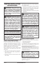
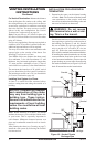
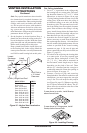
For Vertical Termination: Measure the distance
from the replace ue outlet to the ceiling. Add
the ceiling thickness, the vertical rise in an attic or
second story, and allow for sufcient vent height
above the roof line. You may use one or two 90°
elbows in this vent conguration. See Vertical
Termination Congurations on page 16.
Note: You may use two 45° elbows in place of a
90° elbow. You must follow rise to run ratios when
using 45° elbows.
For two-story applications, restops are required at
each oor level. If an offset is needed in the attic,
additional pipe and elbows will be required.
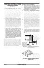
You may use a chase with a vent termination with
exposed pipe on the exterior of the house. See
Installing Vent System in a Chase.
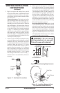
Your DESA direct-vent replace has been tested
for a minimum 3' rise with a maximum 11" wall
thickness. Any horizontal application longer than
12" must provide a minimum of one (1) foot of
vertical rise for every three (3) feet of horizontal run.
The maximum horizontal run is 20' with 8' vertical
rise (see Installation for Horizontal Termination).
The maximum vertical run is 30' (see Installation
for Vertical Termination, page 16).
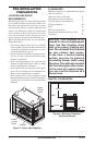
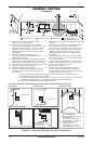
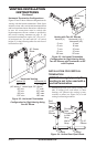
A chase is a vertical box-like structure built to
enclose venting that runs along the outside of a
building.
and construction of the chase
-
Note: When installing in a chase, you should
insulate the chase as you would the outside walls
of your home. This is especially important in
cold climates. Minimum clearance between vent
pipes and combustible materials such as insula-
tion is 1".
After framing the chase (see Framing on page 7)
install the vent system by following the installa-
tion instructions.
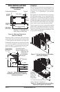
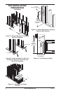
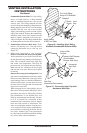
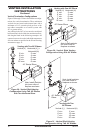
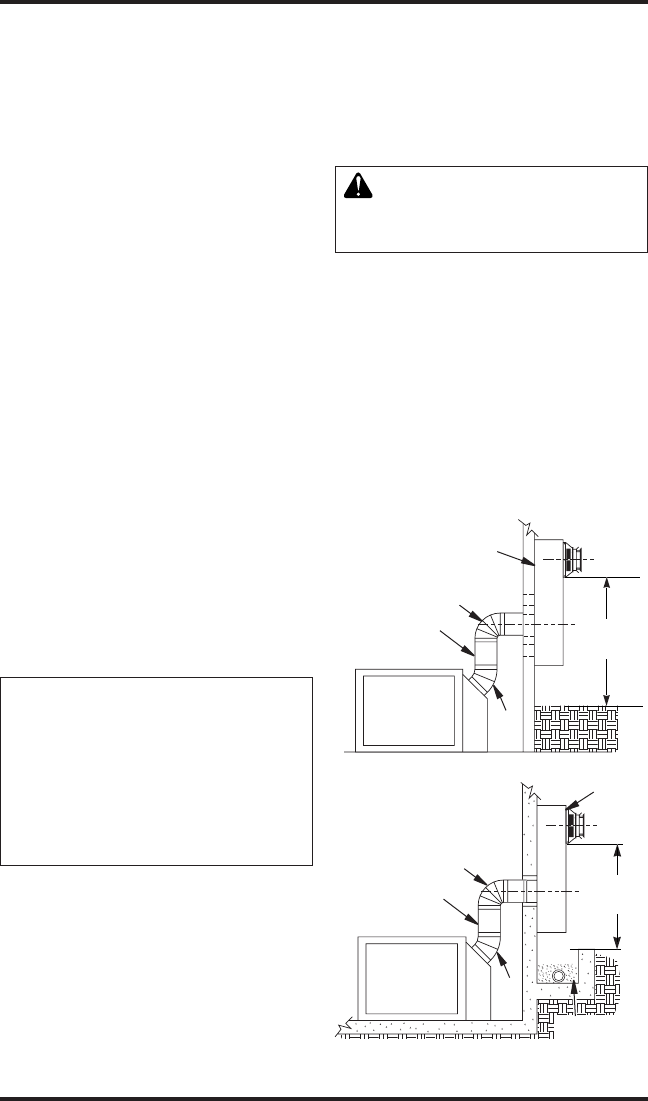
Figure 16 - Snorkel Termination with
Drainage Pipe
Figure 15 - Snorkel Termination
Snorkel
1' Minimum
90º
45º
Adequate
Drainage
Snorkel
1' Minimum
90º
45°
12"
Minimum
12"
Minimum
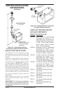
INSTALLATION FOR HORIZONTAL
TERMINATION
1. Determine the route your horizontal venting
will take. Note: The location of the horizontal
vent termination on the exterior wall must
meet all local and national building codes and
must not be blocked or obstructed.
WARNING: Do not recess
vent terminal into a wall or sid-
Snorkel terminations are available for termina-
tions requiring a vertical rise on the exterior of
the building (see Figures 15 and 16). Snorkel
kits are available for rigid pipe applications
only to provide a 14" rise and a 36" rise (see
page 19). Follow the same installation proce-
dures used for standard horizontal terminations.
If installing the snorkel termination to raise the
vent termination from below grade level such
as in a basement installation, you must provide
proper drainage to prevent water from entering
the snorkel termination (see Figure 16). Do not
back ll around the snorkel termination.