


www.desatech.com
56131-F 13
VENTING INSTALLATION
INSTRUCTIONS
Continued
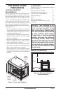
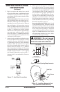
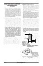
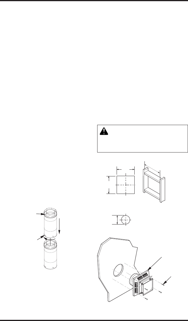
2. Rigid vent pipes and ttings have special
twist-lock connections. Assemble the desired
combination of pipe and elbows to the appli-
ance adaptor with pipe seams oriented towards
the wall or oor.
Twist-lock Procedure: The female ends of the
pipes and ttings have four locking lugs (in-
dentations). These lugs will slide straight into
matching slots on the male ends of adjacent
pipes and ttings. (All connections must be
sealed with high temperature silicone sealant
as specied in the second warning statement
on page 11.) Push the pipe sections together
and twist one section clockwise approximately
one-quarter turn until the sections are fully
locked. See Figure 17. Note: Horizontal runs
of vent must be supported every three feet. Use
wall straps for this purpose.
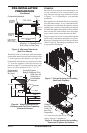
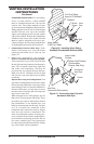
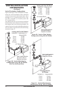
3. Attach vent pipe assembly to the replace using
twist lock connections for rigid pipe or clamp
method for ex pipe. Set replace in front of
its permanent location to insure minimum
clearances. Mark the wall for a 10
3
/
4
" square
hole (for noncombustible material such as
masonry block or concrete, a 8
1
/
2
" diameter
hole is acceptable). See Figure 18. The center
of the hole should line up with the centerline of
the rigid vent pipe. Cut a 10
3
/
4
" x 10
3
/
4
" square
hole through combustible exterior wall (8
1
/
2
"
diameter hole if noncombustible). Frame as
necessary.
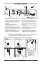
Figure 17 - Vent Pipe Connections
Male
Slots
Female
Locking
Lugs
Rigid Vent
Pipe
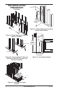
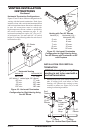
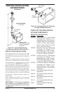
4. Three types of vent caps are available for
horizontal terminations. Two square terminals
are available; one for rigid pipe applications
and one for ex pipe applications. A round
vent termination with a slip t connection is
also provided for rigid pipe applications to
be used when a wall thickness or off spac-
ing must be accommodated. Each may be
purchased as a kit that includes a 45° elbow
and a restop that accommodates a square or
round termination (see Parts List for Venting
Kits and Components, page 19).
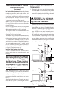
Apply a bead
of non-hardening mastic around the outside
edge of the vent cap. Position the vent cap in
the center of the on the exterior wall with the
arrow on the vent cap pointing up. Attach the
vent cap with four wood screws provided (see
Figure 19). Note: Replace the wood screws
with appropriate fasteners for stucco, brick,
concrete, or other types of siding.
WARNING: Do not recess
Figure 18 - Vent Opening Requirements
(Framing
Detail)
10
3
/4"
10
3
/4" Inside Framing
10
3
/4"
8
1
/2"
Vent
O
pening
Combustible Wall
Vent Opening
Noncombustible Wall
Figure 19 - Installing Horizontal Vent
Cap (Noncombustible Exterior)
Wood Screw
Vent Cap