


www.desatech.com
56131-F 21
INSTALLATION
WALL SWITCH INSTALLATION
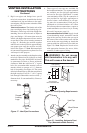
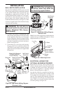
Since the VDVF36TPNEA/TSTEA series uses a 24
VAC current supplied from a transformer mounted
on the ignition module and is prewired for easy
connection to a wall switch (see Figure 34). The
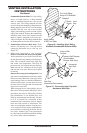
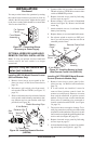
(V)DVF36TPNA/TSTA models use a self gener-
ated millivolt current that allows you to activate
the gas control valve directly without the use of
normal household electricity (see Figure 35). Both
versions are supplied with a wall switch kit for ready
connection and mounting.
WARNING: Do not wire re-
-
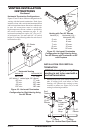
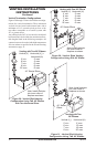
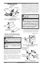
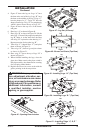
1. To remove the louvers, simultaneously pull
both top end spring latches towards the center
of the appliance until they are disengaged
from locating holes. Repeat for bottom spring
latches and pull louvers outward. Reverse the
procedure to install louvers back onto the ap-
pliance (see Figure 36).
2. Connect the 18 ga. wires from wall switch to
the gas control valve terminals marked TH
and TPTH or to the ignition module using the
pigtails and wire nut connectors supplied with
the appliance.
-
Figure 36 - Removing Louver
Glass
Locating
Holes
Spring
Latch
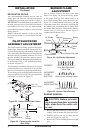
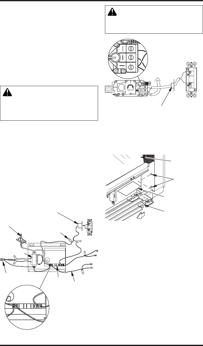
Figure 35 - Wall Switch Wiring Diagram,
Millivolt Units
Note: If any of the original wire supplied must be
replaced, use type 18 AWG-105 degree C (25 feet
length maximum) or equivalent.
O
F
F
P
I
L
O
T
O
N
L
O
H
I
P
I
L
O
T
E A
16AI
7
TPTH TP TH
Wall Switch
(Supplied)
Route Millivolt Wires
(Supplied) Through Gas
Line Conduit Sleeve
To
Thermopile
V1
SW
SI
TS
IND
V2
L1
D
N
G
P.
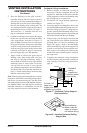
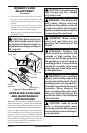
Figure 34 - Wall Switch Wiring Diagram,
Electronic Units
Route 24V (Supplied)
Through Electrical
Conduit Bushing
Electrode
Transformer
Plug 120V AC
To Receptacle
18 AWG
Red Wire
To Gas Valve
Wall Switch
(Supplied)
Make Connections
with Wirenuts
(Supplied)
Ignition
Control
Module
(Back
View)
(Back
View)
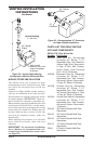
Before blower accessory can be operated, the ap-
pliance outlet box must be properly connected to
a standard 120 VAC power source. This must be
done when the appliance is originally installed.
Refer to Wiring Diagrams on page 33.
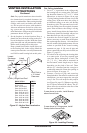
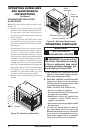
An outlet box with two receptacles has been sup-
plied for your convenience and is located on the
lower right side of the appliance (see Figure 37,
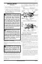
page 22). The variable speed controller is mounted
on a magnetic base and may be positioned any-
where within an accessible distance behind the
louvered opening (see Figure 36).
Recommended
Blower Speed
Control Location
O
F
F
P
I
L
O
T
O
N
L
O
H
I
P
I
L
O
T
E A
16AI
7
TPTH TP TH
V1
SW
SI
TS
IND
V2
L1
D
N
G
P.