


Crestron Commercial Lighting Design Guide Green Light Power Switching
Doc 4775A 29
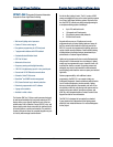
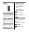
GLS-PLS-
120/277 Power Loss Sensor
The GLS-PLS-120/277 is a 3-Phase Power Loss Sensor
designed for use with Crestron Green Light™ systems to
activate Override mode during a power failure. In response to
a signal from the GLS-PLS-120/277, the lighting system
program can be temporarily overridden while designated
emergency lighting circuits are changed to their override
preset levels and unnecessary lighting and other devices are
shut down to minimize the demand on emergency power
equipment.
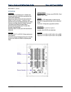
The GLS-PLS-120/277 senses each leg of a 120 or 277 volt
3-phase feed, providing LED indication of the status of each
phase on its front panel. When power is lost on any phase,
the corresponding status LED turns off and a contact closure
is activated on each of two control outputs. Two isolated
control outputs are provided to allow for interfacing with
third-party equipment in addition to the Crestron lighting
system. Each contact closure output is rated for 1A @
24VDC.
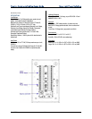
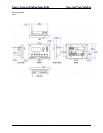
Testing the GLS-PLS-120/277 is facilitated using three test
switches located behind a small cover plate on the front of
the unit. Setting any switch to the TEST position simulates a
loss of power on the corresponding phase leg, providing a
test of the units’ internal circuitry and any connected
equipment.
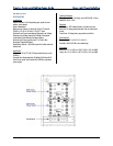
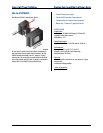
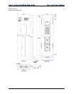
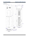
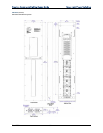
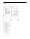
The steel enclosure is designed for mounting to a vertical
surface. Conduit knockouts are provided on the bottom, top,
and both sides. All electrical connections are made via screw
terminals accessed by removing the front panel.
Senses loss of power on each leg of a 3-phase feed
Used to satisfy UL 924 (Emergency Power Equipment)
requirements
Works with 120 or 277 Volt feeds
Designed to activate the Override mode on Crestron
lighting modules
Provides two isolated contact closure outputs
Each output rated 1A @ 24VDC
Includes built-in test function for each phase input
Surface mount enclosure includes conduit knockouts
SPECIFICATIONS
Input Voltages
277V Voltage Range: 235 to 305 Volts AC, 50/60 Hz
120V Voltage Range: 102 to 132 Volts AC, 50/60 Hz
Connections
PHASE A, B, C: (3) Main feed sensing inputs, 277 or 120 Volts
OUTPUTS: (2) Form ‘A’ contact closures, electrically isolated. Both outputs
close when main feed power is removed from any phase sensing input. Rated
1 Amp @ 24 Volts DC
Indicators & Controls
NORMAL A, B, C: (3) Green LEDs, each illuminates when corresponding test
switch is
set to NORMAL and power is present at corresponding phase sensing input
TEST A, B, C: (3) Red LEDs, each illuminates when corresponding test switch
is set to TEST and power is present at corresponding phase sensing input
Test Switches: (3) Slide switches behind cover plate, used to set each
corresponding phase sensing input to TEST mode
Enclosure
Galvanized steel with polycarbonate label overlay; surface mount with integral
mounting flanges top and bottom; 3/4” & 1/2" conduit knockouts top,
bottom, and both sides
Environmental
Temperature: 32° to 104°F (0° to 40°C)
Humidity: 10% to 90% RH (non-condensing)
Heat Dissipation: 51 BTU/Hr
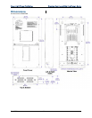
Dimensions
Height: 12.69 x 5.19 x 2.82 in (32.23 x 12.75 x 7.14 cm) HWD
Weight
3.7 lb (1.7 kg)