


Crestron Commercial Lighting Design Guide Green Light Power Switching
Doc. 4775A 17
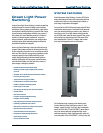
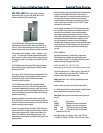
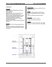
GLPS-SW Green Light Power Switching
Panels (MLO) Main Lug Only and (MCB) Main Circuit
Breaker w/Standard High-Inrush Relays
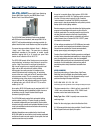
The GLPS-SW Power Switching Panels come standard
with 20A branch circuit breakers, and accept 208Y/120 or
480Y/277 volt feeds terminating to main lugs provided. An
optional back-fed main circuit breaker may also be specified.
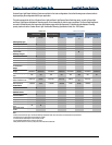
Three panel sizes are available, “Small,” “Medium,” and
“Large.” The panel size is ordinarily determined according
to the number of control circuits specified, ranging from 8 to
42 circuits per panel. Each control circuit is rated for 16A at
100-277V.
The GLPS-SW panels utilize robust 50A relays to handle all
types of lighting loads including electronic ballasts, as well
as motors up to 2 HP.
As an option, GLPS-SW panels may be equipped with 0-10V
fluorescent dimming control substituted in place of some or
all switching circuits. Consult Crestron Sales Support
Services to specify this option.
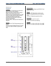
The GLPS-SW panels employ field-replaceable lighting
control modules, with 10 or 16 control circuits per module,
for excellent configurability and service-ability. Each module
includes local relay controls and load state indicators for each
circuit, plus additional controls and indicators for use during
system commissioning.
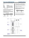
Individual hinged doors are provided on the front of each
GLPS-SW panel for access to the circuit breaker panelboard
and the local controls on each module. As an option, the local
control access door may be omitted.
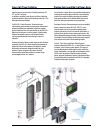
As part of a complete Green Light system, GLPS-SW panels
connect to an IPAC-GL1 lighting control processor (or other 2-
Series control cystem) via the Cresnet control network. An
optional GLA-PWS50 (or equivalent) power supply is also
recommended for each panel to provide backup power to the
lighting modules.
Remote emergency override mode allows the lighting system
program to be overridden while each circuit is set to an
override preset state. The override preset for each circuit is
set using the local controls on the front of each lighting
module. Remote override mode is activated by an external
contact closure from a Crestron GLS-PLS-120/277 power
loss sensor or other devices.
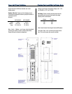
All low-voltage connections to a GLPS-SW panel are made
via a connector block located near the bottom of the panel.
Connections are provided for Cresnet communications,
backup power supply, and emergency override. Crestron
Green Light Power Switching panels are configured to order,
and factory assembled and tested prior to shipping. Each
panel is engineered to provide a clean and manageable
installation with abundant provisions for wire termination and
conduit knockouts. On-site installation is fast and easy with
all termination points clearly labeled and accessible from
the front.
MODEL
NUMBERS
Specifying and ordering a Crestron Green Light Power
Switching panel is facilitated using the following model
number system. Simply fill in the appropriate entry in each
position according to the steps that follow:
GLPS - SW - MLO - 30 - 120 - 10K – ND
GLPS-Relay Type-Feed Type-Number of Ckts-Voltage-AIC Rating-Door Option
The above example is for a “Main Lug Only” panel with 30
“SW” standard high-inrush relays, 120V / 10kAIC circuit
breakers, and no local control access door.
Relay Type: Enter “SW” to specify standard high-inrush
switching relays.
Note: For other relay types, refer to the Selection Guide
0-10V fluorescent dimming is also available. Consult Crestron
Sales Support Services to specify this option.
Feed Type: Choose one of the following to specify the type
of feed:
MLO Main lug only
MCB60 60A back-fed main circuit breaker
MCB80 80A back-fed main circuit breaker
MCB 100 100A back-fed main circuit breaker
MCB 125 125A back-fed main circuit breaker
(available for 277V only)
Note: Main feeds are 3-phase, 4-wire; rated 225A @
120/208V or 250A @ 277/480V. Consult Crestron Sales