


Crestron CHV-TSTAT and CHV-THSTAT Thermostats
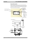
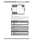
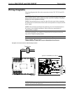
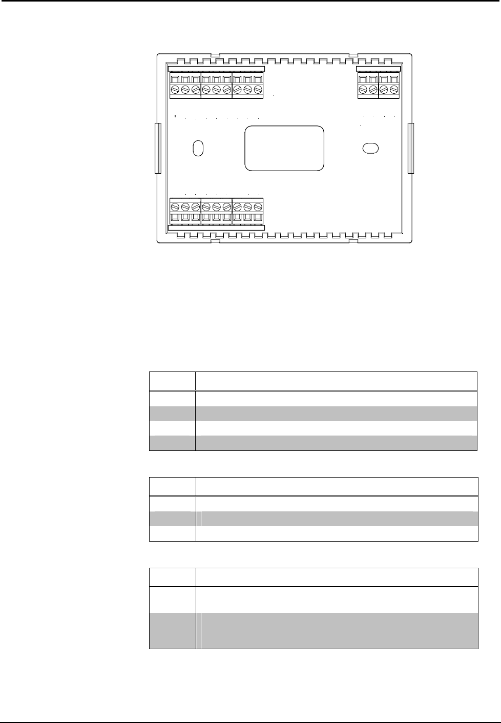
Connection View (Backplate, view from the front with cover removed)
TOP
HUM
RHU
RSR
RSR
RS1
RS2
24(C)
24(R)
24V
Y
Z
G
NETWORK
RH
RC
G
Y/Y1
Y2
O
B
W/W1
W2
Ports
The CHV-TSTAT and CHV-THSTAT have four types of connections on the inside
back plate (refer to graphic above).
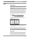
NETWORK (Optional) – provides communication to the control system and Cresnet
power to the CHV-TSTAT and CHV-THSTAT. If making network connections to
Cresnet peripherals, refer to “Network Wiring” on page 7.
CRESNET CONNECTIONS (optional)
PIN DESCRIPTION
24 +24VDC
Y Cresnet Data
Z Cresnet Data
G Ground
REMOTE SENSING CONNECTIONS (optional)
PIN DESCRIPTION
RSR Remote Sensor Returns – Common sensor terminal
RS1 Remote Sensor terminal – Connect the sensor from RS1 to RSR
RS2 Remote Sensor terminal – Connect the sensor from RS2 to RSR
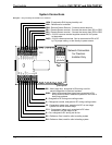
POWER CONNECTIONS (Required)
PIN
DESCRIPTION (refer to System Connections on page 8)
24 (C)
24 VAC common terminal supplies remote 24 VAC power to
thermostat.
24 (R)
24 VAC reference terminal. Can be connected to RH or RC by
P4 jumper setting, or tied directly to power source (refer to
System Connections on page 8)
Operations and Installation Guide – DOC. 8163A Thermostats: CHV-TSTAT and CHV-THSTAT • 5