


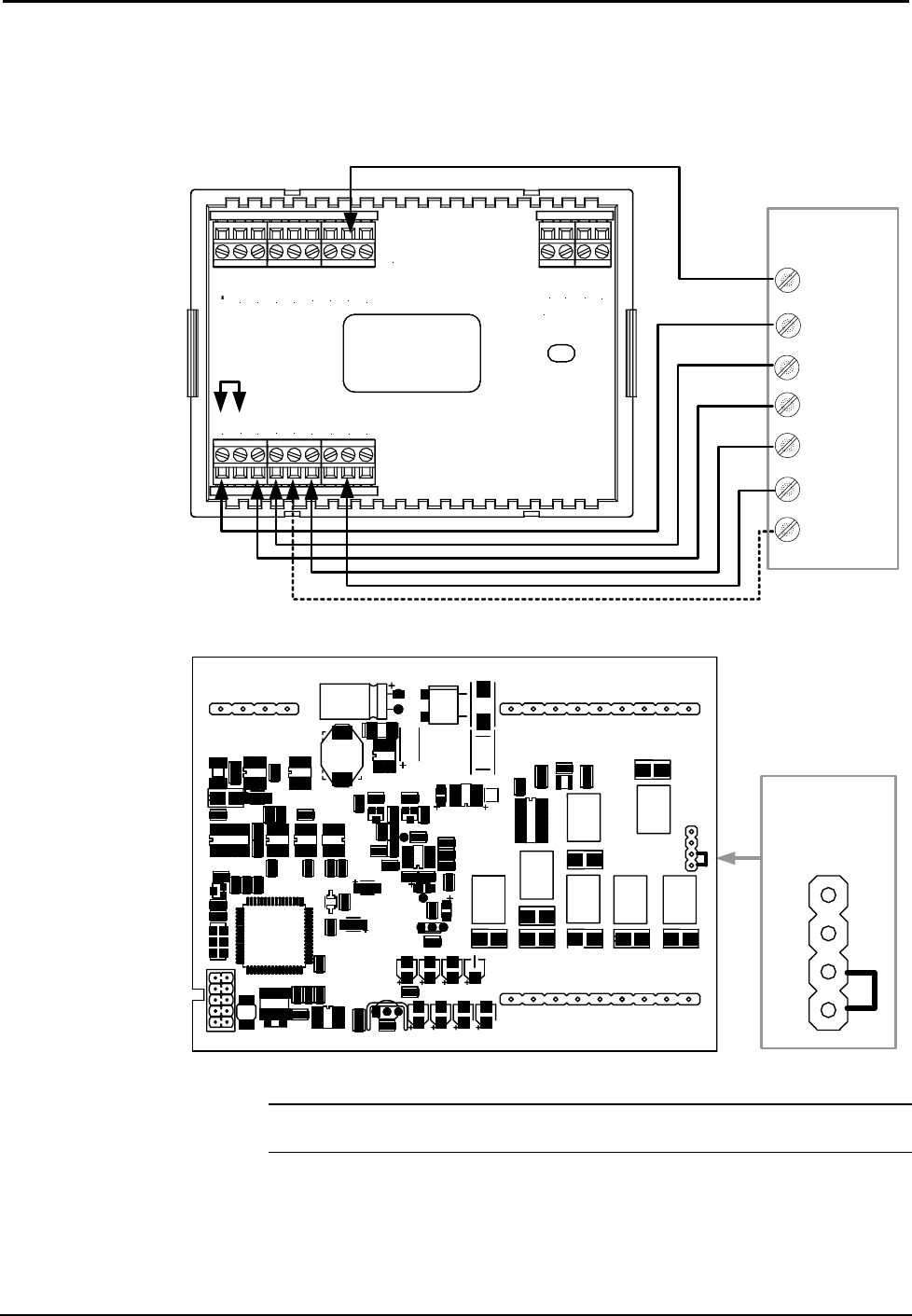
Thermostats Crestron CHV-TSTAT and CHV-THSTAT
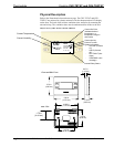
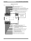
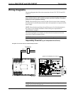
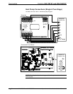
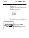
Heat Pump Connections (Single & Two-Stage)
Aux Heat connected to W/W1 – RH and RC jumped together
TOP
HUM
RHU
RSR
RSR
RS1
RS2
24(C)
24(R)
24V
Y
Z
G
NETWORK
RH
RC
G
Y/Y1
Y2
O
B
W/W1
W2
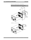
Backplate
Jumper
From RH
to RC
Integrated
Control Unit
C
R
Y
G
O
Aux
Y2
(2
nd
Stage)
3
4
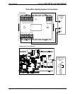
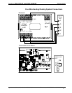
P4
Jumper on
P4 pins 3 & 4
Thermostat Circuit Board
CRESTRON ELECTRONICS
P1
P3
P6
P5
P4
1
2
3
4
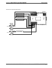
NOTE: For wiring details, refer to the general Heat Pump schematic on the
following page.
12 • Thermostats: CHV-TSTAT and CHV-THSTAT Operations and Installation Guide – DOC. 8163A