


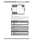
Crestron CHV-TSTAT and CHV-THSTAT Thermostats
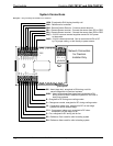
Wiring Diagrams
The wiring diagrams that follow show connections for the CHV-TSTAT and CHV-
THSTAT.
CAUTION: The P4 Jumper Position on the Circuit Board depends on the
power method chosen, and is critical to proper operation. Improper P4 jumper
position can cause equipment damage.
NOTE: Ensure that the power circuits are shut off at the source before connecting
the thermostat. Provide disconnect means and overload protection as required for the
power supply.
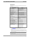
NOTE: Ensure that the transformer has sufficient power for all the thermostats in
the system, or use multiple transformers. Refer to the power requirements in
“Specifications” on page 3.
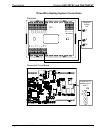
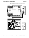
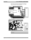
The following diagrams are examples of connections for heat, heat/cool and one-
stage and two-stage heat pump systems.
NOTE: Use either connector O or B as required, for changeover control.
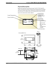
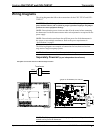
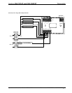
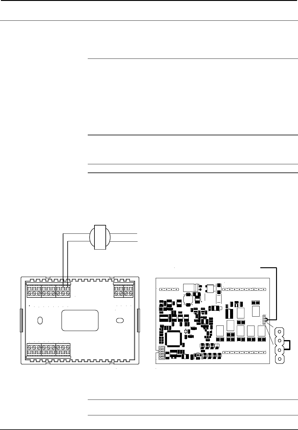
Separately Powered (by an independent transformer)
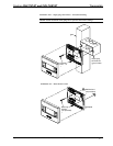
Backplate Connection and Circuit Board Jumper Position
CRESTRON ELECTRONICS
P1
P3
P6
P5
P4
TOP
HUM
RHU
RSR
RSR
RS1
RS2
24(C)
24(R)
24V
Y
Z
G
NETWORK
RH
RC
G
Y/Y1
Y2
O
B
W/W1
W2
1
2
3
4
Jumper on P4 between pins 2 and 3
3
2
P4
Backplate Thermostat circuit board
120 VAC
24 VAC
Transformer
24(C)
24(R)
1
2
3
4
P4
NOTE: The P4 jumper position is critical to proper operation and depends on the
method used to power the thermostat.
Operations and Installation Guide – DOC. 8163A Thermostats: CHV-TSTAT and CHV-THSTAT • 9