


Thermostats Crestron CHV-TSTAT and CHV-THSTAT
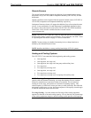
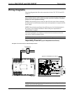
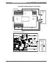
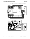
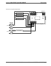
System Connections
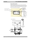
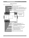
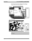
Backplate - view from the front with the cover removed
TOP
HUM
RHU
RSR
RSR
RS1
RS2
24(C)
24(R)
24V
Y
Z
G
NETWORK
RH
RC
G
Y/Y1
Y2
O
B
W/W1
W2
Backplate
24(R) - 24 VAC reference terminal. Can be connected to RH or RC
by P4 jumper setting, or tied directly to power source
24(C) - 24 VAC common terminal supplies remote 24 VAC power
to thermostat
RS2 - Remote Sensor terminal - Connect the sensor from RS2 to RSR
RS1 - Remote Sensor terminal - Connect the sensor from RS1 to RSR
RSR - Remote Sensor Returns - Common sensor terminal
RHU - Reference for humidifier
HUM - Energized to RHU during humidity call
W2 - Heat (stage two), energized to RH during a call for
second stage heat in heat/cool systems
W/W1 - Heat (single stage)/heat (stage one) energized to RH
during a call for heat in heat/cool systems or aux heat in
heat pump systems
B - Energized to RC during non-cooling modes
O - Changeover control, energized to RC during cooling modes
Y2 - Compressor (stage two), energized to RC on two-stage
systems on call for second stage
Y/Y1 - Compressor (stage one), energized to RC when
compressor (or first stage) is run
G - Fan, energized to RC during call for fan
RC - Reference Cool, used for calls to cooling system
RH - Reference Heat, used for calls to heating system
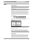
Network Connection
for Crestron
Installer Only
8 • Thermostats: CHV-TSTAT and CHV-THSTAT Operations and Installation Guide – DOC. 8163A