


- 8 -
V
V
V
V
V
V
V
V
V
X
X
X
D
E
B
B
B
C
B
M
B
A
J
K
A
F
L
G
G
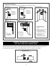
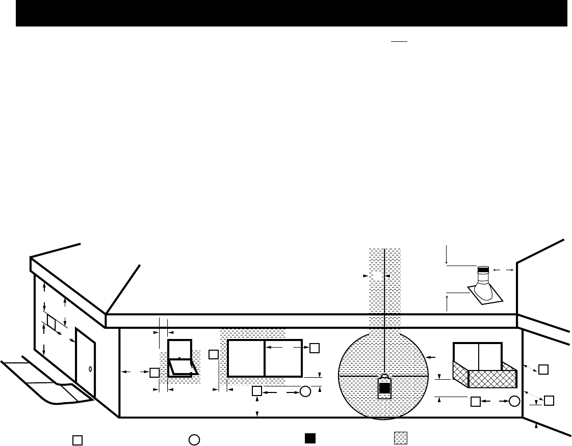
TERMINATION CAP AIR SUPPLY INLET GAS METER RESTRICTED AREA
(TERMINATION PROHIBITED)
H
I
Fixed
Closed
Fixed
Closed
Openable
Openable
Fixed
Closed
G
G
N
N
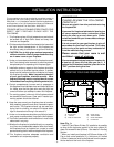
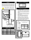
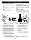
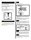
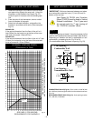
Your fireplace is approved to be vented either through
the side wall, or vertical through the roof.
- Only Majestic venting components specifically
approved and labelled for this fireplace may be
used.
- Minimum clearances between vent pipes and
combustible materials is one (1") inch (25 mm),
except where stated otherwise.
- Venting terminals shall not be recessed into a wall
or siding.
- Horizontal venting must be installed on a level
plane without an inclining or declining slope.
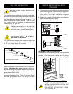
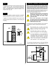
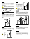
There must not be any obstruction such as bushes, garden
sheds, fences, decks or utility buildings within 24" from the
front of the termination hood.
Do not locate termination hood where excessive snow or
ice build up may occur. Be sure to check vent termination
area after snow falls, and clear to prevent accidental
blockage of venting system. When using snow blowers,
make sure snow is not directed towards vent termination
area.
Location of Vent Termination
It is imperative that the vent termination be located observ-
ing the minimum clearances as shown on this page.
*Check with local codes or in absence of local codes, with
National Fuel Gas Code, ANSI Z223.1 - latest edition for USA, or
CAN 1 B1-149.1 and .1 Installation Code for Canada.
A = clearance above grade, veranda, porch, deck, or
balcony [* 12 inches (305mm) minimum]
B = clearance to window or door that may be opened
12" (306mm).
C = clearance to permanently closed window [minimum
12 inches (305mm) recommended to prevent con-
densation on window]
D = vertical clearance to ventilated soffit located above
the termina/ within a horizontal distance of 24 inches
(610mm) from the centre-line of the terminal [18
inches (458mm) minimum]
E = clearance to unventilated soffit [12 inches (305mm)
minimum
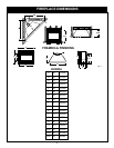
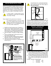
F = clearance to outside comer see next page
G = clearance to inside comer see next page
H = * not to be installed above a meter/regulator assem-
bly within 36 inches (914mm) horizontally from the
centre-line of the regulator
† a vent shall not terminate directly above a side-walk or paved driveway which is located between two single family
dwellings and serves both dwellings *
‡ only permitted if veranda, porch, deck, is fully open on a minimum 2 sides beneath the floor *
* check with local codes, or in the absence of local codes, with National Fuel Gas Code, ANSI Z223.1 - latest edition
for USA, or CAN 1B1-149.1 and .2 Installation Code for Canada.
Note: Local codes or regulations may require different clearances.
I = clearance to service regulator vent outlet [*72 inches
(1828mm) minimum]
J = clearance to non-mechanical air supply inlet to
building or the combustion air inlet to any other
fireplace [ *12 inches (305mm) minimum]
K = clearance to a mechanical air supply inlet [* 72 inches
(1828mm) minimum]
L = † clearance above paved side-walk or a paved
driveway located on public property [*84 inches
(2133mm) minimum]
M = clearance under veranda, porch, deck [*12 inches
(305mm) minimum ‡]
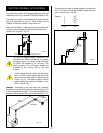
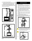
N = Clearance above a roof shall extend a minimum of
24" (610mm) above the highest point when it passes
through the roof surface, and any other obstruciton
within a horizontal distance of 18" (450mm).
GENERAL VENTING INFORMATION