


- 10 -
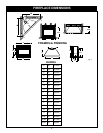
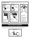
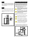
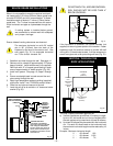
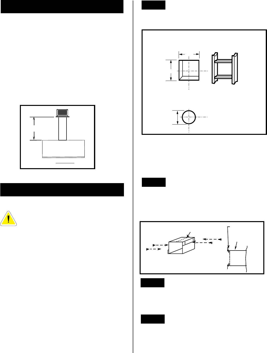
Combustible Walls. Cut a 10-3/8"H x 9-3/8"W (265mm
x 240mm) hole through the exterior wall and frame as
shown. Fig. 14.
Non-Combustible Walls: Hole opening must be 7.5"
(190mm) in diameter. To locate hole centre consult with
appropriate fireplace specifications, page 4.
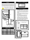
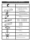
#8
SCREWS(2)
ADJUSTABLE ZERO
CLEARANCE SLEEVE
ADJUSTABLE
ZERO CLEARANCE
SLEEVE
#8
SCREWS(2)
#8
SCREWS(2)
Maximum Length
12" (294mm)
FIRESTOP
Fig. 14
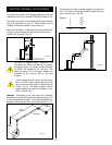
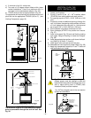
STEP 2
Fig. 15
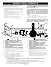
REAR WALL INSTALLATIONS
Minimum clearance between vent pipes and
combustible materials in one (1") inch (25
mm) on sides and bottom and two (2") inch
(50 mm) on top.
(240mm)
9-
3/8
"
10-
3/8
"
(265mm)
7-
1/2
"
(190mm)
Vent Opening —
Combustible Wall
Vent Opening —
Noncombustible Wall
(framing detail)
Measure wall thickness and cut adjustable zero clearance
sleeve parts to proper length (MAXIMUM 12"). Adjust
sleeve to maximum (10-3/8 x 9-3/8) and attach to firestop
with #8 sheet metal screws (supplied). (Fig. 15) Install
firestop assembly.
STEP 3
Measure from fireplace collar face to face of outside wall
(add 2" for vent pipe overlap). Mark pipes and cut to length.
It is very important that the two pipes are flush with the
outside wall once the fireplace is in its final location. Fig. 16.
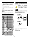
STEP 4
Slip 4" and 7" pipes onto respective flue collars. Make sure
to fix to the fireplace collar the 4" pipe with three (3) screws
before fixing the 7" pipe on the 7" collar. Both pipes must
be on a level plane. Fig. 17.
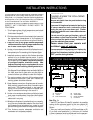
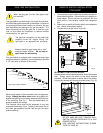
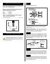
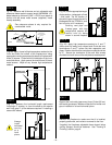
REAR VENTING APPLICATIONS
Minimum clearances between vent pipe and com-
bustible materials are as follows:
Top - 2" (50 mm)
Sides - 1" (25 mm)
Bottom - 1" (25 mm)
Note:
Vent Starter Kit Model 7DVRVT must be
used in rear vent applications.
Maximum Vent Length .........................................20" - Fig. 13
Note: It is not necessary to seal the vent pipe joints
for any rear vent applications.
STEP 1
Locate vent opening on wall.
TOP VIEW
20" (508mm)
Fig. 13