


- 7 -
P
I
L
O
T
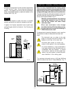
TPTH
TP
TH
SIT VALVE
1/2" GAS SUPPLY
1/2" X 3/8" REDUCER
3/8" NIPPLE
3/8" NIPPLE
3/8" NIPPLE
3/8" X 3/8" SHUT OFF VALVE
3/8" UNION
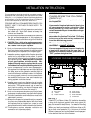
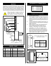
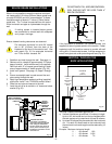
When using copper or flex connector use only approved
fittings. Always provide a union when using black iron
pipe so that gas line can be easily disconnected for burner
or fan servicing. See Fig. 7. See gas specification for
pressure details and ratings.
Typical gas supply installation
Always check for gas leaks with a mild
soap and water solution. Do not use an
open flame for leak testing.
The gas control is equipped with a captured screw type
pressure test point, therefore it is not necessary to provide
a 1/8" test point up stream of the control.
The fireplace valve must not be subjected to any test
pressures exceeding 1/2 psi. Isolate or disconnect this or
any other gas appliance control from the gas line when
pressure testing.
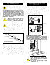
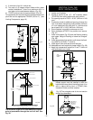
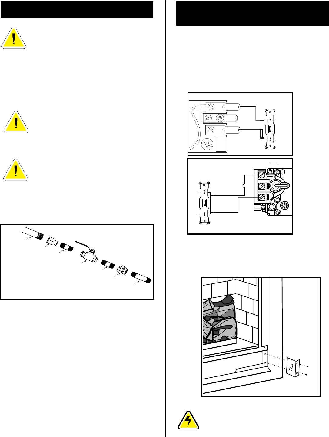
REMOTE SWITCH INSTALLATION
FOR RN/RP
1. Thread wire through the electrical knockout located on
either side of fireplace.. Do not cut wire or insulation on
metal edges. Ensure that wire is protected. Run the
other end to a conveniently located wall receptacle
box.
2. Attach wire to switch and install switch into receptacle
box. Attach cover plate to switch.
3. Connect wiring to gas valve. (Fig. 8/9)
Fig. 9
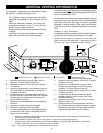
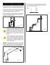
ALTERNATE SWITCH LOCATION:
Remote switch can be installed on either side of the access
door. Simply mount the switch to the switch bracket
provided. Screw the bracket on either side of the frame,
lining up the screws with the pre-punched holes. (Fig. 10)
DO NOT WIRE MILLIVOLT REMOTE WALL
SWITCH FOR GAS FIREPLACE TO A 120V
POWER SUPPLY.
FOR LIGHTING INSTRUCTIONS PLEASE
TURN TO PAGE 30.
Fig. 10
Fig.7
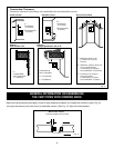
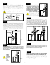
When purging gas line the front glass must
be removed.
The gas pipeline can be brought in through the right side,
left side of the appliance as well as the bottom. Knockouts
are provided at convenient locations to allow for the gas
pipe installation and testing of any gas connection. It is
most convenient to bring the gas line in from the right
side, as this allows fan installation or removal without
disconnecting the gas line.
The gas line connection can be made with
properly tinned 3/8" copper tubing, 3/8"
rigid pipe or an approved flex connector.
GAS LINE INSTALLATION
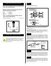
PILOT
ADJ
TH
TP
TP
TH
HONEYWELL VALVE
Fig. 8