


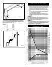
- 36 -
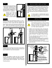
OPTIONAL CERAMIC REFRACTORY
INSTALLATION
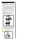
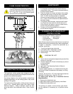
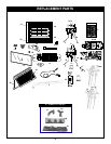
6. Hang Bay Window Frame assembly over existing glass
frame.
Do not remove existing glass frame
7. Re-install top louvre assembly.
Remove all plastic from brass trims
8.
Open the Bottom Bay Louvre door and screw two (2) self
tapping screws (as per step 1 above) to the bottom of the
unit where the hinges were
9. Bottom brass trim is removable when unit is installed with
marble or tile surround which cover the fireplace bottom.
Fig. 76
CERAMIC REFRACTORY
CERAMIC REFRACTORY
BOTTOM BAY LOUVRE
SCREWS
BAY WINDOW FRAME
BOTTOM
BRASS
TOP LOUVRE
SPACERS
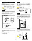
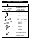
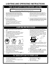
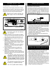
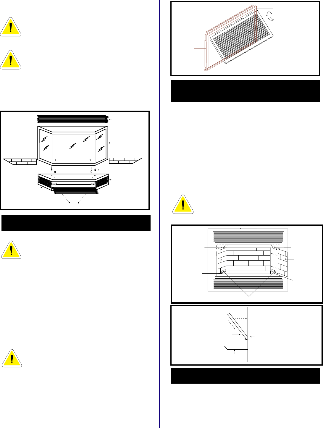
OPTIONAL SCREEN KIT INSTALLATION
To install the Frame Window Screen:
WARNING:
DO NOT install the frame
window screen with the fireplace ON
1- Slide the top edge of the frame window screen
through the slots beneath the main frame window
top trim support.
2- Make the frame window screen parallel to the main
frame window.
3- Slide the bottom edge of the frame window screen
into the space that exist between the glass and the
main frame window bottom trim support.
WARNING: If the fireplace is ON, turn it
OFF and wait until the temperature of the
window screen is cool enough to handle.
To remove the Frame Window Screen:
1- Lift the frame window screen moving it parallel to the
glass.
2- Move the bottom side of the frame window screen
away from the glass.
3- Slide the frame window screen down from the top trim
support.
TOP TRIM
SUPPORT
BOTTOM TRIM SUPPORT
MAIN
FRAME
Fig. 77
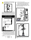
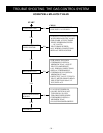
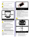
1. Remove glass and logs.
2. Place refractory side supports so that the hole fits over
the screw head on the firebox floor.
3. Place refractory base sides on the floor of the firebox.
4. Place back refractory - small brick edge down into
support (See Fig. 79).
5. Attach adjustable tabs, packed with refractory, onto
the studs found on the top of the firebox using the 2-10/
24 nuts provided.
6. Slide side panels into side supports and behind side
tab and adjust, fitting the ceramic tight to the side of the
firebox. Tighten nuts. Fig. 78.
Mortar lines must be lined up.
Fig. 78
Fig. 79
SIDE
PANEL
SIDE
PANEL
BASE SIDE SUPPORTS
BURNER TRAY
LOG SUPPORT
BACK PANEL
SIDE
TAB
SIDE
TAB
BASE SIDE
REFRACTORY
BASE SIDE
REFRACTORY
FIREBOX
BACK
REAR LOG
SUPPORT
REFRACTORY
BACK PANEL
7. Place refractory base centre in front of the burner.
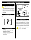
OPTIONAL REMOTE CONTROL
MRC1 - On/Off Button Remote Control
MRC2 - Temperature Control Remote
MRC3 - Temperature Control w/digital display &
24 hour programmable clock
IMT - Wall Mounted Thermostat Control