


- 23 -
X
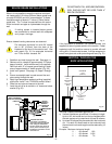
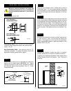
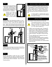
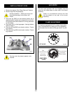
Sealing vent pipe and
firestop gaps with high
temperature sealant will
restrict cold air being
drawn in around fireplace.
Fig. 54
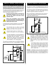
STEP 5
(Fig. 54) Use the appropriate length
of pipe section – telescopic or fixed
– and install. The 20" section of
pipe which goes through the wall is
packaged with the 7TDVSK kit, and
can be cut to suit if necessary.
X
X
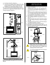
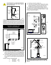
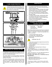
STEP 6
(Fig. 55) Apply high temperature sealant to 4" and 7"
collars one inch away from crimped end. Guide the vent
terminations 4" and 7" collars into their respective vent
pipes. Double check that the vent pipes overlap the collars
by 2". Secure the termination to the wall with screws
provided and caulk around the wall plate to weatherproof.
Fig. 55
STEP 7
Support the horizontal pipes every three (3) feet (92 cm)
with metal pipe straps. Make sure that the horizontal vent
pipe is installed on a level horizontal plane.
STEP 8
Recheck the fireplace to make sure that it is levelled,
properly positioned, and nailed or screwed to the floor.
If applied, the fireplaces adjustable frame drywall strips
(nailing flanges) should be fastened. See "Framing &
Finishing" section.
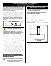
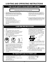
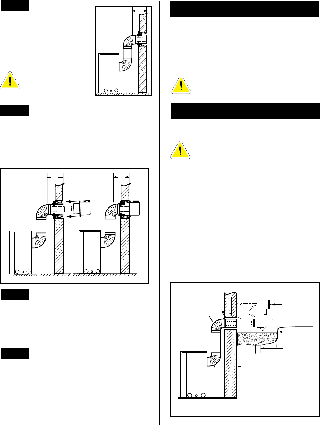
BELOW GRADE INSTALLATIONS
When it is not possible to meet the required vent termi-
nal clearances of 12 inches (305mm) above grade level
a model 7TDVSKS vent kit is recommended. It allows
installation depth of down to 7 inches (178mm) below
grade level. The 7 inches is measured from the centre
of the horizontal vent pipe as it penetrates through the
wall.
If venting system is installed below ground,
we recommend a window well with adequate
and proper drainage.
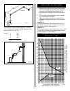
INSTALLATION
Ensure sidewall venting clearances are observed.
The maximum horizontal run with 24" vertical
rise is 36" (915mm) from the back of the
fireplace to the face of the exterior wall. See
vent graph (Fig. 56) for extended horizontal
run if the vertical exceeds 24".
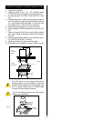
1. Establish vent hole through the wall. See page 23
2. Remove soil to a depth of approximately 16" below
base of snorkel. Install window well (not supplied).
Refill hole with 12" of coarse gravel leaving a clear-
ance of approximately 4" below snorkel. (Fig. 56)
3. Install vent system. See page 23, Steps 2 through
5.
4. Ensure a watertight seal is made around the vent
pipe coming through the wall.
5. Apply high temperature sealant caulking (supplied)
around the 4 and 7 inch 7TDVSKS's snorkel collars.
6. Slide into vent pipe and secure to the wall.
7. Level the soil so as to maintain a 4" clearance below
snorkel (Fig. 56).
Fig. 56
GRAVEL
DRAIN
FIRESTOP
FOUNDATION WALL
WINDOW WELL
7TDVSKS
(SNORKEL)
GROUND
*
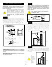
SCREWS
MINIMUM
4" CLEARANCE
ZERO CLEARANCE
SLEEVE IF REQUIRED
7TDVRT90
7TDVRT90
A minimum of 24"/608mm
vertical pipe must be installed
when using the 7DVSKS kit.
The 22" vertical rise (center to
center) of the snorkel may be
included for calculation of max.
horizontal run.
*