


- 5 -
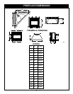
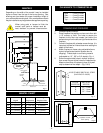
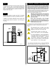
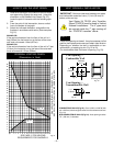
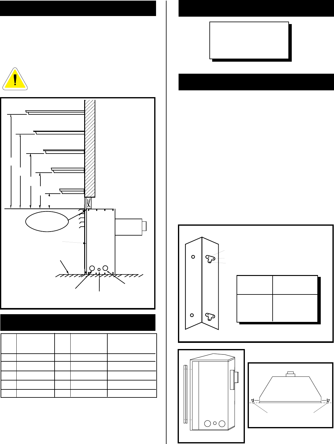
Ref. Mantel Ref. Mantel From Mantel Leg from
Depth Top Louvre Fireplace Side
V 10" (254 mm) A 12" (305 mm) 10" (254mm)
W 8" (203 mm) B 10" (254 mm) 8" (203mm)
X 6" (152 mm) C 8" (203 mm) 6" (152mm)
Y 4" (101 mm) D 6" (152 mm) 4" (101mm)
Z 2" ( 51 mm) E 4" (101 mm) 2" (51mm)
MANTEL CHART
Fig. 3
X
Y
Z
WALL
TOP
LOUVRE
OPENING
E
D
C
B
A
W
V
SIDE VIEW
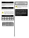
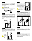
OPTIONAL
HEARTH
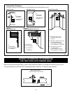
GAS
KNOCK-OUT
ELECTRICAL CABLE
KNOCK-OUT
FRONT GLASS
ELECTRICAL
BOX KNOCK-OUT
MANTELS
Depending on the width of the mantel it may be installed
higher or lower from the top of the louvre opening. See
drawing and chart below for proper installation height of
your combustible mantel piece. Non-combustible mantels
may be installed at any height above the appliance opening.
When using paint or lacquer to finish the
mantel, such paint or lacquer must be
heat resistant to prevent discolouration.
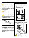
Fig. 5
Fig. 4
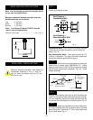
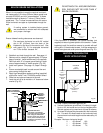
CLEARANCE TO COMBUSTIBLES
1. Choose fireplace location.
2. Place fireplace into position and secure to floor with
1-1/2" screws, or nails. The holes to secure the
fireplace to the floor are located just behind the
access door grill on the left and right hand side of the
fireplace.
3. Frame in fireplace with a header across the top. It is
important to allow for finished face when setting the
depth of the frame.
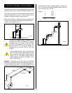
4. Attach fireplace to frame using adjustable frame
drywall strips(located behind access door for
shipping). Preset depth to suit facing material
(adjustable to 1/2" , 5/8" or 3/4" depths). Fig. 4.
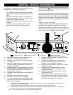
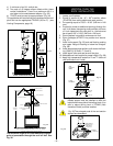
5. Screw through slotted holes in drywall strip and
then screw into pre-drilled holes on fireplace side.
Measure from face of fireplace to face of drywall
strip to determine final depth. (Fig. 5 & 6)
FRAMING AND FINISHING
ADJUSTABLE DRYWALL STRIP
(NAILING FLANGE)
C
A
B
SCREW
POSITION
A
B
C
DRYWALL
DEPTHS
1/2" / 13mm
5/8" / 16mm
3/4" / 19mm
Adjustable 1/2",5/8"
& 3/4" spacing
Fig. 6
Back ........ 0 mm/0 inches
Side......... 0 mm/0 inches
Floor ........ 0 mm/0 inches
Top.......... 0 mm/0 inches