


- 35 -
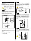
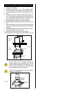
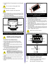
1. Slide fan assembly from the left side into fireplace
opening, line up mounting holes with screw studs on
back of fireplace and fasten with #10-24 hex nuts.
2. Install thermal sensor on bottom of firebox using
#10-24 hex nuts.
3. (Option A) - Place electronic fan speed control
box on bottom of fireplace base, lining up mounting
holes with screw studs. Fasten fan speed control
box with #10-24 hex nuts.
(Option B) - The speed control can be installed in
an electrical box at normal wall switch height for
convenient access.
4. Remove electrical knockout on the side of the
fireplace. (See hard wire or receptacle hook up
instructions).
5. Whether wiring directly to the fan junction box
(Option A) or into the EB1 (electrical receptacle box,
P/N ZA1200, Option B) first ensure cable is secured
using box connector.
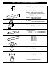
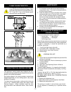
OPTIONAL FAN KIT - FK24
Fan Specifications: 115 Volt 60 HZ 56W
This fan does not need regular maintenance, however
periodic cleaning is required. Check the area under the
control door and in front of the fan and wipe or vacuum
at least once a month during the operating season.
Should this fan require servicing, the
power supply must be disconnected.
The FK-24 comes with the electrical
cord attached.
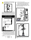
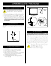
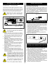
C
B
A
Black
White
Ground
A: SPEED CONTROL
B: TEMPERATURE SENSOR
C: FAN
WIRING INSTRUCTIONS
THE FIREPLACE, WHEN INSTALLED MUST BE
ELECTRICALLY CONNECTED AND GROUNDED IN
ACCORDANCE WITH LOCAL CODES OR, IN THE
ABSENCE OF LOCAL CODES, WITH THE CURRENT
CSA C22.1 CANADIAN ELECTRICAL CODE or for
U.S.A. INSTALLATIONS, FOLLOW LOCAL CODES AND
THE NATIONAL ELECTRICAL CODE, ANSI/NFPA NO.
70.
Hard (DIrect) Wire Hook-Up
First connect ground wire to ground stud located on the
base of either box. Black wire from supply should connect
to the variable speed switch. Alternate speed switch wire
connects to temperature sensor. Alternate lead from
sensor connects to fan. Alternate fan lead connects back
to the white supply wire. (Fig. 74).
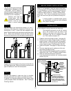
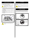
1. Remove 2" knock out. Slide the electrical box back plate
into the back and bottom lances (clips) while fitting the
box connector into the knock out. Fasten into place with
fastening screws provided. Fig. 52.
2. Connect the black positive wire to brass screw (polar-
ized side) of the receptacle. The white wire is connected
to the chrome screw. The ground wire is connected to
the green ground screw of the receptacle. Fit the
receptacle into the electrical box.
3. Screw the cover plate provided to the electrical box.
4. Plug in the FK24 Fan Kit.
Fig. 73
Fig. 75
Fig. 74
FAN SPEED SWITCH
VA LV E
GAS
LINE
ELECTRICAL
BOX
FAN
THERMAL SENSOR
ELECTRICAL BOX
GAS INLET HOLE
INSIDE VIEW
FASTENING
SCREWS
OUTSIDE VIEW
OPTIONAL BAY WINDOW INSTALLATION
1. Remove existing bottom louvre and hinges from fire-
place. (Set aside the two (2) self tapping screws).
2. Remove existing top louvre from fireplace.
3. Remove two (2) pieces of ceramic refractory from Bay
Frame Window; considering that these are very fragile
pieces handle them with special care!
4. Assembly Bay Window Frame to Bottom Bay Louvre by
using four (4) machine screws (from top to bottom), four
(4) nuts (in the bottom) and four (4) spaces (all supplied
with the kit) through the existing four (4) holes in the
bottom of the ay Window Frame and in the top of the
Bottom Bay Louvre. Spacers to be placed between the
Bay Window Frame and the Bottom Bay Louvre.
5. Insert two (2) pieces of ceramic refractory into the Bay
Window Frame as per drawing below.
OPTIONAL EB1 (Receptacle) Hook-Up
Any electrical re-wiring of this fan must
be done by a qualified electrician.
Turn off all power before hook-up.