


21
SERVICE
Water Coil Maintenance
CLOSED LOOP SYSTEM (All Other Water Loop Applica-
tions) — Generally water coil maintenance is not needed for
closed loop systems. However, if the piping is known to have
high dirt or debris content, it is best to establish a periodic
maintenance schedule with the owner so the water coil can be
checked regularly. Dirty installations are typically the result of
deterioration of iron or galvanized piping or components in the
system. Open cooling towers requiring heavy chemical treat-
ment and mineral build-up through water use can also contrib-
ute to higher maintenance. Should periodic coil cleaning be
necessary, use standard coil cleaning procedures, which are
compatible with both the heat exchanger material and copper
water lines. Generally, the more water flowing through the unit,
the less chance for scaling. However, flow rates over 3 gpm per
ton can produce water (or debris) velocities that can erode the
heat exchanger wall and ultimately produce leaks.
OPEN LOOP SYSTEM (Direct Ground Water) — If the
system is installed in an area with a known high mineral con-
tent (125 ppm or greater) in the water, it is best to establish a
periodic maintenance schedule with the owner so the coil can
be checked regularly. Should periodic coil cleaning be neces-
sary, use standard coil cleaning procedures, which are compati-
ble with the heat exchanger material and copper water lines.
Generally, the more water flowing through the unit, the less
chance for scaling. Therefore, 1.5 gpm per ton is recommended
as a minimum flow. Minimum flow rate for entering water
temperatures below 50 F is 2.0 gpm per ton.
Filters — A clean filter must be used to obtain maximum
performance. Filters should be inspected every month under
normal operating conditions. It is especially important to pro-
vide consistent washing of these filters (in the opposite direc-
tion of the normal airflow) once per month. Never operate a
unit without a filter, severe system damage can occur.
Condensate Drain — In areas where airborne bacteria
may produce an algae build-up in the drain pan, it may be nec-
essary to remove and treat the drain pan chemically with an al-
gaecide approximately every three months to minimize the
problem. The condensate pan may also need to be cleaned peri-
odically to ensure indoor air quality. The condensate drain can
pick up lint and dirt, especially with dirty filters. Inspect the
drain twice a year to avoid the possibility of plugging.
Compressor — Conduct annual amperage checks to in-
sure that amp draw is no more than 10% greater than indicated
on the serial data plate.
Fan Motors — All units have lubricated fan motors. Peri-
odic maintenance oiling is not recommended, as it will result in
dirt accumulating in the excess oil and cause eventual motor
failure. Conduct annual dry operation check and amperage
check to ensure amp draw is no more than 10% greater than in-
dicated on serial data plate.
Evaporator Coil — The air coil must be cleaned to ob-
tain maximum performance. Check once a year under normal
operating conditions and, if dirty, brush or vacuum clean. Care
must be taken not to damage the aluminum fins while cleaning.
Cabinet — The cabinet can be cleaned using a mild
detergent. Do not allow water to stay in contact with the cabi-
net for long periods of time to prevent corrosion of the cabinet
sheet metal.
Refrigerant System — To maintain sealed circuit integ-
rity, do not install service gages unless unit operation appears
abnormal. Verify that air and water flow rates are at proper lev-
els before servicing the refrigerant circuit.
TROUBLESHOOTING
Lockout Modes —
If the microprocessor board is flash-
ing a system warning and the unit is locked out and not run-
ning, the lockout can be cleared from the microprocessor by a
momentary shutdown of incoming line voltage (208-vac or
230-vac). A lockout that still occurs after line voltage shudown
means that the fault still exists and needs to be repaired.
HIGH-PRESSURE LOCKOUT (HP) — The high-pressure
lockout will occur if the discharge pressure of the compressor
exceeds 600 psi. The lockout is immediate and has no delay
from the time the high-pressure switch opens to the lockout.
Upon lockout the compressor will be deenergized immediately.
The blower will be deenergized 15 seconds after the compres-
sor is deenergized.
LOW-PRESSURE LOCKOUT (LP) — The low-pressure
lockout will occur if the suction pressure falls below 40 psi for
30 continuous seconds. The compressor will then be deener-
gized and the blower will deenergize 15 seconds after the com-
pressor is deenergized.
FREEZE PROTECTION 1 LOCKOUT — The freeze pro-
tection 1 lockout will occur if the liquid line temperature falls
below the set point (15 F or 30 F) for 30 continuous seconds.
See DIP switch 2 description in the DIP Switch Settings and
Operation section. The compressor will then be deenergized
and the blower will deenergize 15 seconds after the compressor
is deenergized.
FREEZE PROTECTION 2 LOCKOUT — The freeze pro-
tection 2 lockout will occur if the air coil temperature falls be-
low the set point (32 F) for 30 continuous seconds. See DIP
switch 2 description in the DIP Switch Settings and Operation
section. The compressor will then be deenergized and the
blower will deenergize 15 seconds after the compressor is
deenergized.
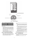
CONDENSATE OVERFLOW 1 LOCKOUT (CO1) —
The unit contains one condensate overflow sensor located in
the chassis drain pan below the air coil. A condensate lockout
will occur if the sensor senses condensate for 30 continuous
seconds. The compressor will then be deenergized and the
blower will deenergize 15 seconds after the compressor is
deenergized.
OVER/UNDER VOLTAGE PROTECTION — If the unit
control voltage is less than 18-vac or greater than 30-vac the
unit will shut down all inputs immediately. Once the voltage
WARNING
Electrical shock can cause personal injury or death. When
installing or servicing system, always turn off main power
to system. There may be more than one disconnect switch.
WARNING
The installation and servicing of air-conditioning equip-
ment can be hazardous due to system pressure and electri-
cal components. Only trained and qualified service
personnel should install, repair, or service air-conditioning
equipment.
CAUTION
Use caution when cleaning the coil fins as the fin edges are
extremely sharp. Failure to heed this warning could result
in personal injury.