


13
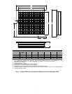
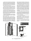
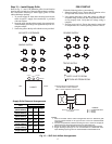
Step 6 — Wire Field Power Supply
Connections
ELECTRICAL–LINE VOLTAGE — All field-installed wir-
ing, including electrical ground, must comply with the National
Electrical Code (NEC) as well as all applicable local codes. Re-
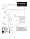
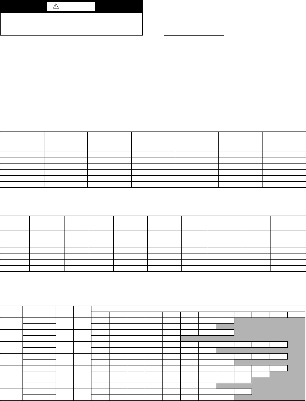
fer to Tables 4 and 5 for fuse sizes. Refer to Table 6 for blower
speed wiring. See Fig. 10 for field connections or the electrical
diagram located on the back of the electrical compartment front
panel. All electrical connections must be made by the installing
(or electrical) contractor. All final electrical connections must
be made with a length of flexible conduit to minimize vibration
and sound transmission to the building.
General Line Voltage Wiring
— Be sure the available
power is the same voltage and phase shown on the unit
serial plate. Line and low voltage wiring must be done in
accordance with local codes or the NEC, whichever is appli-
cable.
POWER CONNECTION
Units Equipped with Disconnect
— Connect incoming line
voltage to the disconnect switch and ground wire to the ground
lug provided inside the electrical compartment.
Units without Disconnect
— Line voltage connection is made
by connecting the incoming line voltage wires to the line
side(s) of the contactor.
208/230-VAC OPERATION — All commercial 208/230-v
units are factory wired for 208-v single-phase operation. For
230-v single-phase operation the primary voltage to the trans-
former must be changed. Remove the red lead from the com-
pressor contactor capping it with a wire nut and connecting the
orange 230-vac lead wire from the transformer to the compres-
sor contactor.
NOTE: Failure to change the primary voltage lead when using
240-vac line voltage may result in electrical component dam-
age and intermittent system failure.
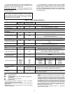
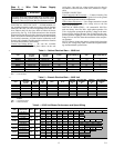
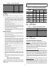
Table 4 — Cabinet Electrical Data — 50VS Unit
LEGEND
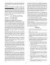
Table 5 — Chassis Electrical Data — 50VS Unit
LEGEND
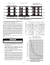
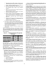
Table 6 — 50VS Unit Blower Performance and Speed Wiring
NOTE: Operation not recommended in shaded area.
WARNING
Electrical shock can cause personal injury or death. When
installing or servicing system, always turn off main power
to system. There may be more than one disconnect switch.
UNIT
SUPPLY
VOLTAGE
V-Hz-Ph
MOTOR
VOLTAGE
V-Hz-Ph
FAN MOTOR
FLA (A)
MOTOR POWER (W)
MIN CIRCUIT
AMP
MAX FUSE SIZE (A)
50VSA,B 208/230-1-60 208/230-1-60 0.30 130 6.2 15
50VSC,D 208/230-1-60 208/230-1-60 0.40 142 8.3 15
50VSE,F 208/230-1-60 208/230-1-60 0.88 180 13.3 25
50VSG,H 208/230-1-60 208/230-1-60 1.18 240 13.6 25
50VSI,J 208/230-1-60 208/230-1-60 1.60 304 15.1 25
50VSK,L 208/230-1-60 208/230-1-60 1.80 368 22.4 35
50VSM,N 208/230-1-60 208/230-1-60 2.06 442 25.3 40
FLA — Full Load Amps
UNIT
SUPPLY
VOLTAGE
V-Hz-Ph
MIN
CIRCUIT
AMP
MAX FUSE
SIZE
(A)
COMPRESSOR
(LRA)
COMPRESSOR
(RLA)
COOLING
CURRENT
(A)
MAX COOLING
CURRENT
(A)
HEATING
CURRENT
(A)
MAX HEATING
CURRENT
(A)
50VSA,B 208/230-1-60 6.2 15 20 4.7 3.27 4.0 3.75 4.60
50VSC,D 208/230-1-60 8.3 15 27 6.3 4.40 4.0 5.25 6.25
50VSE,F 208/230-1-60 13.3 25 42 9.9 6.30 5.4 7.07 8.80
50VSG,H 208/230-1-60 13.6 25 42 9.9 6.70 7.6 7.50 9.00
50VSI,J 208/230-1-60 15.1 25 46 10.8 8.20 8.0 9.20 11.70
50VSK,L 208/230-1-60 22.4 35 70 16.5 11.00 10.4 12.20 14.10
50VSM,N 208/230-1-60 25.3 40 79 18.6 12.70 16.0 13.65 16.50
LRA — Locked Rotor Amps
RLA — Rated Load Amps
UNIT
FAN SPEED
AND WIRING
RATED
CFM
MIN
CFM
EXTERNAL STATIC PRESSURE (in. wg)
0 0.01 0.05 0.1 0.15 0.2 0.25 0.3 0.35 0.4 0.45 0.5
50VSA,B
LOW (Black)
360 260
361 358 341 321 294 268 235 177
HI (Blue) 316 310 294 278 262 233 206
50VSC,D
LOW (Blue)
420 300
424 421 398 376 350 315 280 240
HI (Red) 361 358 341 321 305
50VSE,F
LOW (Black)
540 390
551 549 535 521 509 490 476 460 441 420 400
HI (Blue) 470 465 455 439 428 412 397
50VSG,H
LOW (Blue)
630 455
626 622 604 592 577 561 548 530 513 495 476
HI (Red) 551 549 535 521 509 490 476 460
50VSI,J
LOW (Orange)
820 600
821 817 814 812 802 790 775 747 684 654 621
HI (Brown) 768 765 762 759 751 742 722 683 653 625
50VSK,L
LOW (Black)
1080 780
1081 1075 1070 1049 1024 931 880 843 801
HI (Blue) 956 951 942 928 911 835 809
50VSM,N
LOW (Blue)
1220 850
1222 1219 1194 1160 1129 1088 1057 1017 961
HI (Red) 1102 1096 1091 1070 1044 949 897 860
311