


16
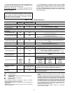
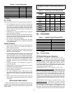
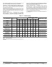
Table 8 — Braided Water Hose Bend Allowances
NOTE: Do not allow hoses to rest against sharp edges or structural
building components. Compressor vibration may cause hose failure
and vibration transmission through the hoses to the structure, caus-
ing noise complaints.
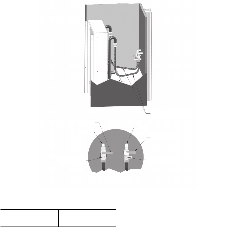
7. Slide the chassis part way into the cabinet. Match the
WATER IN hose to the WATER IN tube on the chassis
and the WATER OUT hose to the WATER OUT tube.
Tighten the swivel connection keeping the copper tube
parallel to the sides of the chassis, and then tighten the
hose to the copper making sure the hose hangs straight
without twisting or turning.
NOTE: The copper union and the hose union is to be
hand tight plus an additional
1
/
4
of a turn, always use
back-up wrench on the fittings being tightened.
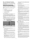
Step 10 — Install Chassis into the Cabinet
1. Open the unit water valves and check piping for leaks.
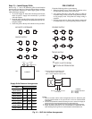
2. Complete electrical connections between cabinet and
chassis by mating the quick-connect plugs on the chassis
cable to the plugs located in the bottom surface of the
blower deck, directly under the control box.
3. Before installing the return panel, perform the following
checks:
a. Ensure that fan wheel rotates freely and does not
rub against housing. If rough handling during ship-
ping has caused fan wheel to shift, adjust as neces-
sary.
b. Verify that water piping connections to the chassis
are complete and that unit service valves which
were closed during flushing have been opened.
c. Verify that power between the cabinet and chassis
is properly connected.
d. After the system has been filled and system pump
is started, all connections should be re-checked for
water leaks. Carrier WILL NOT be responsible or
liable for damage caused by any water leaks from a
field-installed water connection(s).
4. Re-attach the upper electrical access panel. Do not start
the unit with access panel removed; system lockout and
possible equipment damage can occur.
Step 11 — Install Return Panel
1. Install the provided adhesive-backed gasket material on
the outer perimeter of the cabinet to seal the return panel
to the cabinet.
2. Install the cabinet return panel. Refer to Fig. 4 and 5.
HOSE DIAMETER (in.) BEND ALLOWANCE (in.)
1
/
2
2
5
/
8
3
/
4
4
1
/
2
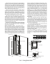
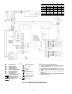
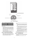
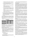
VALVE DETAIL VIEW
PRESSURE/TEMP TEST PLUG
BALANCING VALVE
RETURN
BALL VALVE
SUPPLY
PRESSURE/TEMP TEST PLUG
1/2-in. FLEX HOSE (50VSC-VSH UNITS)
3/4-in. FLEX HOSE (50VSI-VSN UNITS)
a50-8293
Fig. 11 — Hose Kit Installation