


18
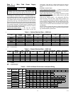
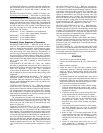
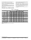
Table 9 — Limits of Operation
LEGEND
*Requires additional insulation when operating below the dew point.
4. Unit fan: Manually rotate fan to verify free rotation and
ensure that blower wheel is secured to the motor shaft. Be
sure to remove any shipping supports if needed. DO NOT
oil motors upon start-up. Fan motors are pre-oiled at the
factory. Check unit fan speed selection and compare to
design requirements.
5. Condensate line: Verify that condensate line is open and
properly pitched toward drain.
6. Water flow balancing: Record inlet and outlet water tem-
peratures for each heat pump upon start-up. This check
can eliminate nuisance trip outs and high velocity water
flow that could erode heat exchangers.
7. Unit controls: Verify that the microprocessor DIP (dual
in-line package) switches are set for proper operation and
system configuration.
System Checkout
1. System water temperature: Check water temperature for
proper range and also verify heating and cooling set
points for proper operation.
2. System pH: Check and adjust water pH if necessary to
maintain a level between 6 and 8.5. Proper pH promotes
longevity of hoses and fittings.
3. System flushing: Verify that all hoses are connected end
to end when flushing to ensure that debris bypasses the
unit heat exchanger, water valves and other components.
Water used in the system must be potable quality initially
and clean of dirt, piping slag, and strong chemical clean-
ing agents. Verify that all air is purged from the system.
Air in the system can cause poor operation or system
corrosion.
4. Cooling tower/boiler: Check equipment for proper set
points and operation.
5. Standby pumps: Verify that the standby pump is properly
installed and in operating condition.
6. System controls: Verify that system controls function and
operate in the proper sequence.
7. Low water temperature cutout: Verify that low water
temperature cutout controls are provided for the outdoor
portion of the loop. Otherwise, operating problems may
occur.
8. System control center: Verify that the control center and
alarm panel have appropriate set points and are operating
as designed.
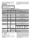
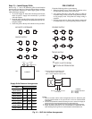
FIELD SELECTABLE INPUTS
Jumpers and DIP switches on the control board are used to
customize unit operation and can be configured in the field. See
Tables 10 and 11 for heat pump and BacNet control board DIP
switch settings.
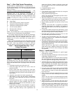
Table 10 — Heat Pump Control Board (PCB)
LEGEND
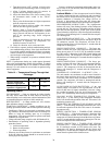
Table 11 — BacNet™ Control Board (PCB)
LEGEND
DIP Switch Settings and Operation
DIP SWITCH 1 (Test Mode = Off/Normal Mode = On)
Test Mode
— Test mode is used to speed up the operation
sequence of the unit, therefore creating a more timely trouble-
shooting technique. All time delays are shorted by 10 times
with the exception of the high-pressure lockout which is
instantaneous regardless of which mode the switch is posi-
tioned. DIP switch 1 must be placed into the Normal mode to
resume proper operation of the unit.
DIP SWITCH 2 (FP 1 at 15 F = Off/FP 1 at 32 F = On)
Water Side Freeze Protection Setting
— DIP switch 2 is used
to determine the loop freeze protection setting. Depending on
the brine concentration of the liquid source, the temperature
can be set at 15 F or 32 F. The switch MUST be set to the “On”
position if pure water is used as the source brine. This is nor-
mally the case in open loop systems. Set the DIP switch to the
“Off” position for closed loop systems that contain a brine con-
centration that allows liquid temperatures to fall to, or below,
15 F.
DIP SWITCH 3 (Tstat at Comm = off/tstat at 24-vac = On)
Thermostat Selection
— DIP switch 3 is used to select the
type of thermostat that will be used to control the unit. A digi-
tal communicating thermostat can be purchased with the unit
that will allow all fault signals to be displayed on the
thermostat. This allows for efficient troubleshooting and does
not require that the technician access the electrical control box
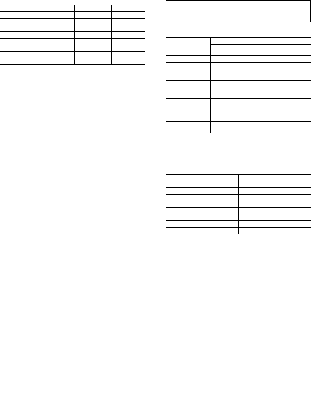
Air Limits Cooling (F) Heating (F)
Ambient Air Maximum 50 50
Ambient Air Minimum 100 85
Rated Ambient Air 80.6 68
Rated Entering Air (db/wb) 80.6/66.2 68
Entering Air Maximum (db/wb) 100/83 80
Entering Water Minimum* 30 20
Entering Water (Normal) 50-110 30-70
Entering Water Maximum 120 90
db — Dry Bulb
wb — Wet Bulb
IMPORTANT: Jumpers and DIP switches should only
be clipped when power to control board has been turned
off.
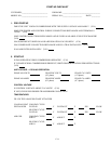
DIP SWITCH
NUMBER
PROTOCOL
No
Network
BacNet LonWorks
Modbus
(PC)
1 — Test/Normal ON ON ON ON
2 — FP1 15 F/32 F ON ON ON ON
3 — Tstat Comm/
24-vac
ON or
OFF
OFF OFF OFF
4 — RV Cooling
Off/On
ON ON ON ON
5 — Com2/Com1 ON OFF OFF OFF
6 — Com2 Modbus
Address
OFF OFF OFF OFF
7 — Com2 Modbus
Address
OFF OFF OFF OFF
8 — Com2 Modbus
Address
OFF OFF OFF OFF
DIP — Dual In-Line Package
PC — Personal Computer
PCB — Printed Circuit Board
DIP SWITCH NUMBER POSITION OFF/ON
1 ON
2 OFF
3 OFF
4 OFF
5 OFF
6 OFF
7 OFF
8 OFF
DIP — Dual In-Line Package
PCB — Printed Circuit Board