


2
INSTALLATION
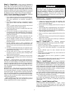
Step 1 — Check Jobsite —
Installation, operation and
maintenance instructions are provided with each unit. Before
unit start-up, read all manuals and become familiar with the
unit and its operation. Thoroughly check out the system before
operation. Complete the inspections and instructions listed
below to prepare a unit for installation. See Table 1 for unit
physical data.
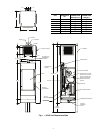
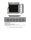
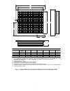
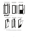
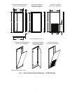
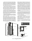
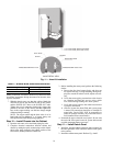
The 50VS units are designed for indoor installations. Units
are typically installed in a floor-level closet or a small mechan-
ical room. Be sure to allow adequate space around the unit for
servicing. See Fig. 1-5 for unit dimensions.
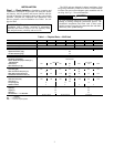
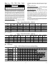
Table 1 — Physical Data — 50VS Unit
LEGEND
IMPORTANT: This equipment is designed for indoor
installation ONLY. Extreme variations in temperature,
humidity and corrosive water or air will adversely affect
the unit performance, reliability and service life.
CAUTION
To avoid equipment damage, do not use units as a source of
heating or cooling during the construction process. The
mechanical components and filters used in these units
quickly becomes clogged with construction dirt and debris
which may cause system damage.
UNIT 50VSA,B 50VSC,D 50VSE,F 50VSG,H 50VSI,J 50VSK,L 50VSM,N
COOLING CAPACITY (Btuh)
9,200 11,700 16,500 18,000 22,500 28,500 32,700
HEATING CAPACITY (Btuh)
12,500 16,000 22,500 24,500 31,000 38,000 45,000
CABINET WEIGHT (lb)
120 170
CHASSIS WEIGHT (lb)
99 105 119 122 187 198 205
COMPRESSOR (1 each)
Rotary Scroll
High Side Pressure (psig)
550
Low Side Pressure (psig)
170
FACTORY REFRIGERANT CHARGE R-410A (oz) 27.5 27.5 36.7 41.6 49.4 63.5 61.8
FAN DATA
Fan Motor Type/Speeds
PSC/2 speed
Blower Wheel Size (Depth x Width) (in.)
Std/High Static
7.08 x 6.69 9.21 x 9.99
Airflow (cfm)
370 450 540 640 820 1120 1300
Static Pressure (in. wg)
0
WATER/CONDENSATE SIDE DATA
Flow Rate (gpm)
2.6 3.2 4.5 5.2 6.5 8.5 9.5
Water Connection Size (FPT) (in.)
1/2 3/4
Water Side Pressure Drop (psi)
5.8 5.8 11.5 11.8 4.8 7.2 10.2
Condensate Connection Size (in.)
3/4
AIR COIL DATA
Total Face Area (sq ft)
1.48 1.48 1.81 1.48 1.48 1.81 1.48
Tube Size (in.)
3/8
Fin Spacing (FPI)
12 14 10
Number of Rows
2 323
CABINET DATA
Depth (in.)
18 24
Height (in.)
88 88
Width (in.)
18 24
Standard Filter -- 1 in. Washable
14-1/4 x 18-1/2 14-1/4 x 22-1/2 19 x 28-3/4
FPI — Fins Per Inch
PSC — Permanent Split Capacitor