


10
All riser modifications necessitated by variations in floor-to-
floor dimensions including cutting off or extending risers is the
sole responsibility of the installing contractor.
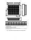
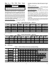
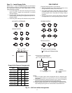
Additional expansion compensation must be made in the
riser system in the field where movement is expected to exceed
the factory allowances. Figure 9 displays the expansion charac-
teristics of risers compared to water temperature differential.
Assuming a minimum water temperature of 20 F and a
maximum water temperature of 120 F, the temperature differ-
ence of 100 F indicates 90 feet of riser will expand or contract
1 inch. To eliminate stress, a riser system must be anchored at
least once to the building structure. Technical information on
pipe expansion, contraction and anchoring can be found in the
ASHRAE HVAC Systems and Equipment Handbook and vari-
ous other technical publications. Riser expansion and the an-
choring of each unit is the responsibility of the design engineer
and installing contractor.
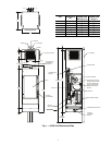
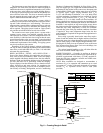
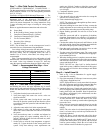
RISER CONNECTIONS — Install cabinet with risers as
follows:
1. Move cabinet into position.
2. Be sure that all the copper fittings are clean and free of
dirt. Raise the cabinet upright and lower it into the riser
from the floor below.
NOTE: The top of each riser is equipped with a 3 in. deep
swaged connection. There is sufficient extension at the
bottom to allow insertion of approximately 2 in. of the
riser into the swaged top of the riser below.
3. Center risers in the pipe chase and shim the cabinet level.
Plumb risers in two planes to assure proper unit operation
and condensate drainage.
4. Attach the cabinet assembly to the floor and the building
structure on at least two sides using sheet metal angles
(field provided). A field-provided base vibration dampen-
ing pad can be used to help eliminate transfer of any vi-
bration to the structure. If vibration dampening pads are
used some rough-in dimensional changes will need to be
considered before installation due to style and thickness
of the pads. Additional anchorage can be provided by in-
stalling brackets at the top of the cabinet (field provided).
5. DO NOT attach drywall studs to the equipment cabinet.
CAUTION
Keep risers off the floor while moving the cabinet. Failure
to heed this warning could result in equipment damage.
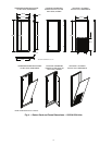
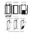
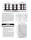
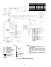
Fig. 7 — System Piping Arrangements
DIRECT RETURN REVERSE RETURN REVERSE RETURN
WITH A COMMON REVERSE
RETURN RISER
a50-8332
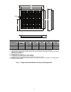
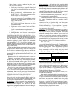
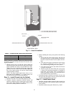
Fig. 8 — Friction Loss of Risers
PIPE SIZE
3/4 inch
1 inch
1-1/4 inch
1-1/2 inch
2 inch
2-1/2 inch
Water Flow Rate - GPM
Pressure Drop - Ft Water/100 Ft of Riser
2 ft/s
3 ft/s
4 ft/s
Water Velocity (feet per second)
5 ft/s
6 ft/s
3.0 4.0 5.0 6.0 7.0 8.0 10 20 30 40 50 60 70 80 100
3.0 4.0 5.0 6.0 7.0 8.0 10 20 30 40 50 60 70 80 100
15
10
9.0
8.0
7.0
6.0
5.0
4.0
3.0
2.0
1.0
15
10
9.0
8.0
7.0
6.0
5.0
4.0
3.0
2.0
1.0
a50-8333
Fig. 9 — Allowable Riser Lengths Between
System Expansion Loops
1-1/2”
1”
Water Temperature Difference - F
Riser Length for 1 in. and 1-1/2 in. Expansion - Ft
550
500
450
400
350
300
250
200
150
100
50
0
20 40 60 80 100 120 140 160
a50-8334