


15
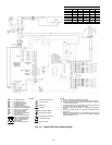
Step 7 — Wire Field Control Connections
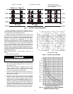
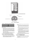
STANDARD 24-V THERMOSTAT CONNECTIONS —
The thermostat should be wired directly to the microprocessor
board terminals labeled P1 to the corresponding terminals
(R,C,Y1,Y2,O,G).
Installation of Optional Wall-Mounted Thermostat
— The
unit can be controlled with a remote 24-volt surface mounted
thermostat such as the Honeywell TH5320U1001 or
TH6320U1000 series thermostat. Refer to instructions pro-
vided with remote thermostat for wiring instructions using
2 stages of heating and 2 stages of cooling for a heat pump
system.
Below are typical thermostat connections and color codes.
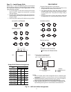
Rc Power (Red)
R R+Rc joined by factory jumper wire (Red)
Y Compressor Contactor (Stage 1) (Yellow)
Y2 Compressor Contactor (Stage 2) (Blue)
C 24-vac Common (White)
O Reversing Valve (Orange)
G Fan Relay (Green)
NOTE: The terminal block on the microprocessor board is
removable for ease of thermostat wiring installation.
Low-voltage wiring between the unit and the wall thermo-
stat must comply with all applicable electrical codes (i.e., NEC
and local codes), and be completed before the unit is
installed. Use of six-wire, color-coded, low-voltage cable is
recommended.
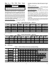
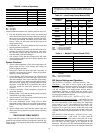
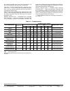
Table 7 lists recommended wire sizes and lengths to install
the thermostat. The total resistance of low voltage wiring must
not exceed 1 ohm. Any resistance in excess of 1 ohm may
cause the control to malfunction because of high voltage drop.
Table 7 — Recommended Wire Gage — Low
Voltage Thermostat
Step 8 — Clean and Flush System — Cleaning
and flushing the unit is the most important step to ensure
proper start-up and continued efficient operation of the system.
Follow the instructions below to properly clean and flush the
system.
1. Verify that electrical power to the unit is off.
2. Verify that supply and return riser service valves are
closed at each unit.
3. Fill the system with water, leaving the air vents open.
Bleed all air from the system but do not allow the system
to overflow. Check the system for leaks and make any re-
quired repairs.
4. Adjust the water and air level in the expansion tank.
5. With strainers in place, start the pumps. Systematically
check each vent to ensure that all of the air is bled from
the system.
6. Verify that make-up water is available and adjusted to
properly replace any space remaining when all air is
purged. Check the system for leaks and make any addi-
tional repairs if needed.
7. Set the boiler to raise the loop temperature to approxi-
mately 85 F. Open the drain at the lowest point in the
system. Verify that make-up water replacement rate
equals rate of bleed. Continue to bleed the system until
the water appears clean or for at least three hours which-
ever is longer.
8. Completely drain the system.
Flush risers as follows:
1. Close shut-off valves at each unit on the riser except the
shut-off valve on the top floor.
2. Flush solution through supply riser.
NOTE: The solution passes through the top floor connec-
tion down the return riser.
3. When the building has more than 10 floors, connect the
supply and return run outs on the top two floors to divide
the water flow and reduce pressure drop at the pump.
4. Repeat flushing procedure for each set of risers in the
building.
5. Refill the system and add in a proportion of trisodium
phosphate approximately one pound per 150 gallons of
water. Reset the boiler to raise the loop temperature to
about 100 F.
6. Circulate the solution for between 8 and 24 hours. At the
end of this period, shut off the circulating pump and drain
the solution. Repeat system cleaning if needed.
7. Open the supply and return riser service valves at each
unit. Refill the system and bleed off all air.
8. Test the system pH with litmus paper. The system water
should have a pH of 6 to 8.5. Add chemicals as appropri-
ate to maintain pH levels.
9. When the cleaning process is complete, remove the short-
circuited hoses. Reconnect the hoses to the proper supply,
and return the connections to each of the units. Refill the
system and bleed off all air.
NOTE: DO NOT use “Stop Leak” or similar chemical
agent in this system. Addition of chemicals of this type to
the loop water will foul the heat exchanger and inhibit
unit operation.
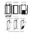
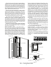
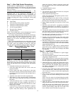
Step 9 — Install Hose Kit
1. Refer to Fig. 11 for an illustration of a typical supply/
return hose kit assembly.
2. Pipe joint compound or Teflon tape is not necessary when
using factory-supplied hose kits.
NOTE: When anti-freeze is used, ensure that it is compat-
ible with Teflon tape and pipe joint compound that may
have been applied to other pipe fittings in the system.
3. Attach the flex hoses. Unpack and examine hose kit. Re-
move all shipping and/or packing material such as rubber
bands, plastic caps, and styrofoam. Hose kit should con-
tain 2 hoses, one balancing valve with shutoff, one shut-
off, and 2 hose adaptors.
4. Locate the valves inside the unit cabinet marked WATER
IN and WATER OUT. Attach the hoses to the water
valve. Always use a back-up wrench when tightening the
hose to the valve.
5. If the valves are removed to attach the hoses, be sure the
O-ring is in the valve before attaching to the union in the
cabinet.
NOTE: The valve union is to be hand tight plus an addi-
tional
1
/
4
of a turn; always use back-up wrench on the fit-
tings being tightened.
6. Attach flex hoses. Let the universal ends of the hoses
hang inside the cabinet. See Table 8 for bend allowances.
NOTE: Be sure the valve handles and P/T ports are in a
position that enables them to be opened and closed and
used for system readings. Check the swivel ends of the
hoses. Gaskets must be in the hose for proper seal.
WIRE SIZE (gage)
MAXIMUM RUN (UNIT TO
THERMOSTAT) (ft)
22 30
20 50
18 75
16 125
14 200