


14
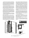
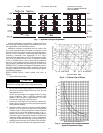
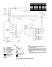
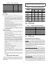
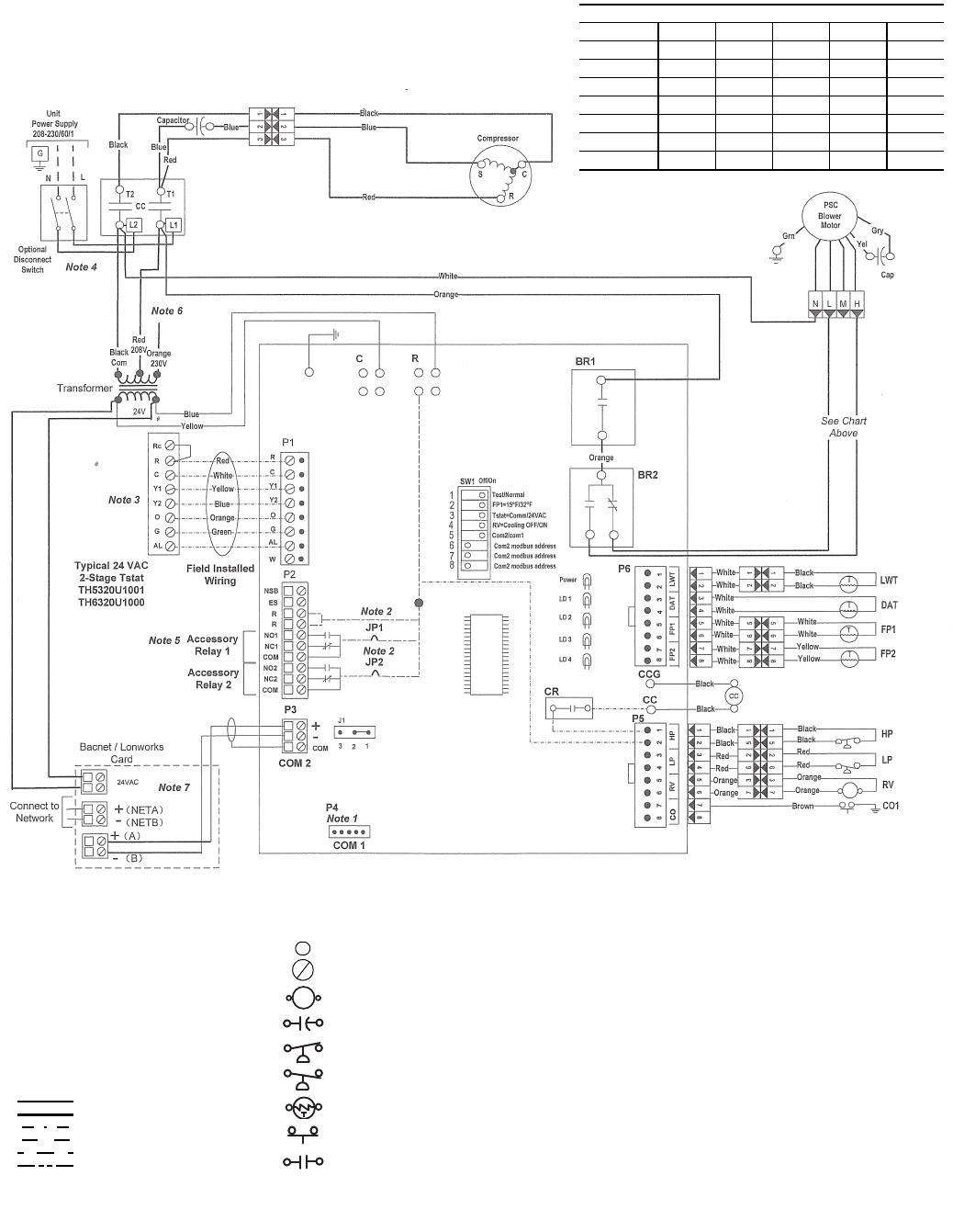
BLOWER SPEED WIRING
Unit Orange Brown Black Blue Red
50VSA,B Low High — — —
50VSC,D —LowHigh— —
50VSE,F — — Low High —
50VSG,H ———LowHigh
50VSI,J Low High — — —
50VSK,L — — Low High —
50VSM,N ———LowHigh
a50-8352
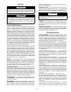
NOTES:
1. Used for optional communicating thermostat.
2. Cut JP1 or JP2 for dry contact output accessory relay 1 and 2.
3. If a single stage thermostat is used, place a jumper wire between
Y1 and Y2 at P1 terminal.
4. If the disconnect option is not installed, connect the power to the
L1 and L2 lugs on the compressor contactor.
5. Accessory relays 24-vac maximum, activated by compressor
output.
6. For 230-v operation, remove the red wire and replace with the
orange wire.
7. Before connecting BacNet™ or LonWorks® card, connect com-
municating thermostat, then short J1 (2-3). If adding terminating
resistance, short J1 (1-2).
BR1 — Fan Relay Speed 1
BR2 — Fan Relay Speed 2
CC — Compressor Contactor
CO — Condensate Overflow
CR — Compressor Relay
DAT — Discharge Air Temperature
FP1 — Freeze Protection Water Side
FP2 — Freeze Protection Air Side
HP — High Pressure Switch
LP — Low Pressure Switch
LWT — Leaving Water Temperature
RV — Reversing Valve
Factory Low Voltage Wiring
Factory High Voltage Wiring
Field Low Voltage Wiring
Field Line Voltage Wiring
Optional Block
Internal PCB Connection
Quick Connect Terminal
Screw Terminal
Relay Coil
Capacitor
High Pressure Switch
Low Pressure Switch
Temperature Thermistor
Condensate Switch
Relay Contacts
LEGEND
Fig. 10 — Typical 50VS Unit Control Wiring