


20
f. Turn thermostat to “OFF” position. A hissing noise
indicates proper functioning of the reversing valve.
g. Allow 5 minutes between tests for pressure to
equalize before beginning heating test.
h. Adjust the thermostat to the lowest setting. Place
the thermostat mode switch in the “HEAT”
position.
i. Slowly raise the thermostat to a higher temperature
until the compressor activates.
j. Check for warm air delivery within a few minutes
after the unit has begun to operate.
k. Refer to Table 9. Check the temperature of both
entering and leaving water. If temperature is within
range, proceed with the test. If temperature is out-
side of the operating range, check refrigerant
pressures.
l. Check air temperature rise across the air coil when
compressor is operating. Air temperature rise
should be between 20 and 30 F.
m. Check for vibration, noise, and water leaks.
6. If unit fails to operate, perform troubleshooting analysis
(see troubleshooting section). If the check described fails
to reveal the problem and the unit still does not operate,
contact a trained service technician to ensure proper diag-
nosis and repair of the equipment.
7. When testing is complete, set system to maintain desired
comfort level.
NOTE: If performance during any mode appears abnormal
refer to the troubleshooting section of this manual. To obtain
maximum performance, the air coil should be cleaned before
start-up. Use a coil cleaner for use on indoor evaporator refrig-
eration equipment.
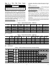
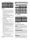
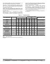
Table 12 — Temperature Change Through Heat
Exchanger
Operating Limits
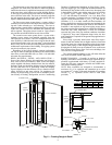
ENVIRONMENT — Units are designed for indoor installa-
tion only. Never install units in areas subject to freezing or
where humidity levels could cause cabinet condensation (such
as unconditioned spaces subject to 100% outside air).
POWER SUPPLY — A voltage variation of 10% of name-
plate utilization voltage is acceptable.
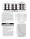
STARTING CONDITIONS — Starting conditions vary de-
pending upon model number and are based upon the following:
• Conditions in Table 9 are not normal or continuous operat-
ing conditions. Minimum/maximum limits are start-up con-
ditions to bring the building space up to occupancy
temperatures. Units are not designed to operate under these
conditions on a regular basis.
• Voltage utilization range complies with ARI Standard 110.
• Determination of operating limits is dependent primarily
upon three factors:
a. Ambient temperature
b. Return air temperature
c. Water temperature
• When any one of these factors is at minimum or maximum
levels, the other two factors should be at normal levels to
ensure proper unit operation.
Extreme variations in temperature and humidity and/or cor-
rosive water or air will adversely affect unit performance, reli-
ability, and service life.
Lockout Mode — If the microprocessor board is flashing
a system warning and the unit is locked out and not running,
the lockout can be cleared from the microprocessor by a mo-
mentary shutdown of incoming line voltage (208-vac or
230-vac). A lockout that still occurs after line voltage shut-
down means that the fault still exists and needs to be repaired.
HIGH-PRESSURE LOCKOUT (HP) — The high-pressure
lockout will occur if the discharge pressure of the compressor
exceeds 600 psi. The lockout is immediate and has no delay
from the time the high-pressure switch opens to the lockout.
Upon lockout the compressor will be deenergized immediately.
The blower will be deenergized 15 seconds after the compres-
sor is deenergized.
LOW-PRESSURE LOCKOUT (LP) — The low-pressure
lockout will occur if the suction pressure falls below 40 psi for
30 continuous seconds. The compressor will then be de-
energized and the blower will deenergize 15 seconds after the
compressor is deenergized.
FREEZE PROTECTION 1 LOCKOUT — The freeze pro-
tection 1 lockout will occur if the liquid line temperature falls
below the set point (15 F or 30 F) for 30 continuous seconds.
See DIP switch 2 description in the DIP Switch Settings and
Operation section. The compressor will then be deenergized
and the blower will deenergize 15 seconds after the compressor
is deenergized.
FREEZE PROTECTION 2 LOCKOUT — The freeze pro-
tection 1 lockout will occur if the air coil temperature falls be-
low the set point 32 F for 30 continuous seconds. See DIP
switch 2. The compressor will then be deenergized and the
blower will deenergize 15 seconds after the compressor is
deenergized.
CONDENSATE OVERFLOW 1 LOCKOUT (CO1) —
The unit contains one condensate overflow sensor located in
the chassis drain pan below the air coil. A condensate lockout
will occur if the sensor senses condensate for 30 continuous
seconds. The compressor will then be deenergized and the
blower will deenergize 15 seconds after the compressor is
deenergized.
OVER/UNDER VOLTAGE PROTECTION — If the unit
control voltage is less than 18-vac or greater than 30-vac the
unit will shut down all inputs immediately. Once the voltage
has reached acceptable levels the unit microprocessor will
power “On” automatically and resume previous operation.
LEAVING WATER TEMPERATURE SENSOR FAIL-
URE (LWT) — If the leaving water temperature thermistor
fails it will not affect the operation of the unit. This sensor is for
monitoring purposes only.
DISCHARGE AIR TEMPERATURE SENSOR FAILURE
(DAT) — If the discharge temperature thermistor fails it will
not affect the operation of the unit. This sensor is for monitor-
ing purposes only.
FREEZE PROTECTION 1 TEMPERATURE SENSOR
FAILURE (FP1) — If the freeze protection 1 thermistor fails
for 30 continuous seconds an FP1 lockout will occur. The
compressor will then be deenergized and the blower will deen-
ergize 15 seconds after the compressor is deenergized. The sen-
sor must be replaced if this lockout occurs.
FREEZE PROTECTION 2 TEMPERATURE SENSOR
FAILURE (FP2) — If the freeze protection 2 thermistor fails
for 30 continuous seconds an FP2 lockout will occur. The
compressor will then be deenergized and the blower will
deenergize 15 seconds after the compressor is deenergized. The
sensor must be replaced if this lockout occurs.
WATER FLOW GPM
RISE IN
COOLING (°F)
DROP IN
HEATING (°F)
For Closed Loop: Ground
Source or Closed Loop
Systems at 3 gpm per ton
9-12 4-8
For Open Loop: Ground Water
Systems at 1.5 gpm per ton
20-26 10-17