


19
to determine the unit error. If a digital communicating thermo-
stat is used DIP switch 3 must be set in the “Off” position. If a
24-vac thermostat is used set DIP switch 3 into the “On”
position.
DIP SWITCH 4 (RV at Cooling = Off/RV at Cooling = On)
Reversing Valve Operation
— DIP switch 4 is used to deter-
mine the reversing valve (RV) position in the Cooling mode
(deenergized/energized). This function is used only when a 24-
vac thermostat is used and is determined by the reversing valve
output of the thermostat in the Cooling mode. If the thermostat
deenergizes the reversing valve in the Cooling mode then set
the DIP switch in the “Off” position. If the thermostat ener-
gizes the reversing valve in the Cooling mode set the DIP
switch in the “On” position.
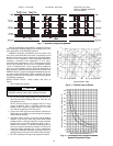
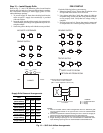
DIP Switch 5 (Com2 = Off/BacNet™ or LonWorks®)
(Com1 = On/Communicating Thermostat)
DIP Switch 6 (Com2 modbus address)
DIP Switch 7 (Com2 modbus address)
DIP Switch 8 (Com2 modbus address)
Standard 24-vac Sequence of Operation
RANDOM START DELAY — When the unit is first pow-
ered “On” the control microprocessor will generate a random
number to determine the start delay of the compressor opera-
tion (3 to 5 minutes). This delay is used to prevent multiple
units from cycling “On” at the same time. The purpose is to
prevent a large power load on the building electrical system af-
ter a power outage. After the number, or delay time, is generat-
ed the microprocessor will use this time to determine the mini-
mum amount of time that must be delayed before the compres-
sor is cycled “On” after a demand is received from the
thermostat.
ANTI SHORT CYCLING DELAY — After the random
start delay is generated the microprocessor will use this time to
determine the minimum amount of time that must be delayed
before the compressor is cycled “On” after a demand is
received from the thermostat. This allows the refrigerant sys-
tem to equalize in pressure and prevents short-cycling of the
compressor.
MINIMUM COMPRESSOR RUNTIME — The minimum
compressor runtime of each cycle, heating or cooling, is
60 seconds. Once the compressor is energized it will not de-
energize, even if the thermostat input is removed, until the min-
imum runtime is satisfied.
COOLING FIRST STAGE (Y1, O) — When the micropro-
cessor receives (Y1, O) at the 24-vac thermostat input connec-
tion the unit will proceed with the cooling first stage sequence.
The microprocessor must receive these signals for 2 continu-
ous seconds before it recognizes the inputs as valid. Once the
input signals are determined to be valid the reversing valve will
energize/deenergize after 5 seconds.
The microprocessor will then verify that the anti-short cy-
cling delay has been satisfied. Once the anti short cycling delay
has been satisfied the compressor and will cycle “On.” The
blower will cycle “On” in low speed 15 seconds after the com-
pressor is cycled “On.”
COOLING SECOND STAGE (Y1, Y2, O) — When the mi-
croprocessor receives (Y1, Y2, O) at the 24-vac thermostat in-
put connection the unit will proceed with the cooling second
stage sequence. The microprocessor must receive these signals
for 2 continuous seconds before it recognizes the inputs as val-
id. Once the input signals are determined to be valid the revers-
ing valve will energize/deenergize after 5 seconds. The micro-
processor will then verify that the anti short cycling delay has
been satisfied. Once the anti short cycling delay has been satis-
fied the compressor and will cycle “On.” The blower will cycle
“On” in high speed 15 seconds after the compressor is cycled
“On.”
HEATING FIRST STAGE (Y1) — When the microproces-
sor receives (Y1) at the 24-vac thermostat input connection the
unit will proceed with the cooling first stage sequence. The mi-
croprocessor must receive these signals for 2 continuous sec-
onds before it recognizes the inputs as valid. Once the input
signals are determined to be valid the reversing valve will
energize/deenergize after 5 seconds. The microprocessor will
then verify that the anti short cycling delay has been satisfied.
Once the anti short cycling delay has been satisfied the com-
pressor and will cycle “On.” The blower will cycle “On” in low
speed 15 seconds after the compressor is cycled “On.”
HEATING SECOND STAGE (Y1, Y2) — When the micro-
processor receives (Y1, Y2) at the 24-vac thermostat input
connection the unit will proceed with the heating second stage
sequence. The microprocessor must receive these signals for
2 continuous seconds before it recognizes the inputs as valid.
Once the input signals are determined to be valid the reversing
valve will energize/deenergize after 5 seconds.
The microprocessor will then verify that the anti short cy-
cling delay has been satisfied. Once the anti short cycling delay
has been satisfied the compressor and will cycle “On.” The
blower will cycle “On” in high speed 15 seconds after the com-
pressor is cycled “On.”
FAN ONLY MODE (G) — The fan only mode can be used
only with a 24-vac thermostat and will energize the low speed
blower when a (G) input has been received at the 24-vac ther-
mostat input connection. When the input is removed the blow-
er will deenergize immediately.
START-UP
1. Turn on the line power to all heat pumps.
2. Turn the thermostat fan position to “ON.” Blower should
start.
3. Balance airflow at registers.
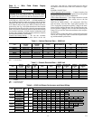
4. Adjust all valves to their full open positions. Room
temperature should be within the minimum-maximum
ranges of Table 9. During start-up checks, loop water
temperature entering the heat pump should be between
60 and 95 F.
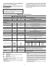
5. Two factors determine the operating limits of the 50VS
heat pumps: supply-water temperature and the return-air
temperature. When any one of these factors is at a mini-
mum or maximum level, the other factor must be at a nor-
mal level to ensure proper unit operation.
a. Adjust the unit thermostat to the warmest setting.
Place the thermostat mode switch in the “COOL”
position. Slowly reduce thermostat setting until the
compressor activates.
b. Check for cool air delivery at the unit grille within
a few minutes after the unit has begun to operate.
NOTE: Units have a 3 to 5 minute time delay in
the control circuit that can be eliminated on the
microprocessor control board. See test mode
described in the DIP Switch Settings and Opera-
tion section.
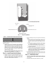
c. Check the elevation and cleanliness of the conden-
sate lines. Dripping may be a sign of a blocked
line. Check that the condensate trap is filled to pro-
vide a water seal.
d. Refer to Table 12. Check the temperature of both
entering and leaving water. If temperature is within
range, proceed with the test. If temperature is
outside of the operating range, see Troubleshooting
section.
e. Check air temperature drop across the air coil
when compressor is operating. Air temperature
drop should be between 15 and 25 F.