


Manufacturer reserves the right to discontinue, or change at any time, specifications or designs without notice and without incurring obligations.
Catalog No. 04-53500019-01 Printed in U.S.A. Form 50TFQ-9SI Pg 54 9-05 Replaces: 50TFQ-7SI
Book 1 4
Tab 5a 5a
Copyright 2005 Carrier Corporation
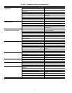
INDEX
Access panels 18
Barometric flow capacity 20
Carrier Comfort Network 14
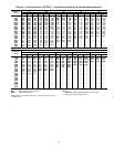
Charging chart, refrigerant 48,49
Clearance 3, 6
CO
2
sensor
Configuration 25
Settings 23, 25
Compressor
Mounting
44
Rotation 44
Condensate drain
Cleaning 47
Location 3
Control circuit
Wiring 12
Wiring raceway 12
Convenience outlet 10, 11, 13
Defrost board 12, 13
Demand control ventilation 24
Dehumidification 25
Dimensions 2,6
Ductwork 3
EconoMi$er2 18
Components 18
4to20mAcontrol 20
Wiring 20
EconoMi$er IV 18-25
Components 18
Damper 24
Dry bulb changeover 21
Enthalpy changeover 22
Inputs and outputs 53
Troubleshooting 49, 50
Wiring 19
Electrical connections 7
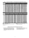
Electrical data 8-11
Electric heat 8
Enthalpy changeover set points 23
Factory-installed options 12-25
Convenience outlet 13
EconoMi$er2 18-20
EconoMi$er IV 18-25
Manual outdoor air damper 13
Novar controls 13
PremierLink™ controls 14-16
Filter
Cleaning 48
Installation 19
Size 5
Freeze protection thermostat 5,48
Heat anticipator settings 12,13
High flow valves 44
High pressure switch 5, 48
Horizontal units 3
Indoor air quality 14, 22
Indoor coil 5
Cleaning 47
Indoor fan motor 5
Lubrication 48
Motor data 26
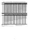
Performance 28-43
Pulley adjustment 26
Pulley setting 5, 27
Speed 5
Low pressure switch 5, 48
Manual outdoor air damper 13
Mounting
Compressor 44
Unit 3
Novar controls 13
Operating sequence
Cooling 45
EconoMi$er2 45-47
EconoMi$er IV 45
Heating 45
Outdoor air hood 14,19
Outdoor air inlet screens 44
Cleaning 48
Outdoor coil 5
Cleaning 47
Outdoor fan 5
Adjustment 48
Physical data 5
Potentiometer 22
Power supply
Wiring 7
PremierLink controls 14-16
Pressure, drop
Electric heat 27
Return air 20
Outdoor air 20
Pre-start-up 44
Pressure switches
High pressure 5
Low pressure 5
Refrigerant
Charge 5,48, 49
Type 5
Refrigerant service ports 44
Replacement parts 48
Return air filter 5, 44
Return air temperature sensor 22
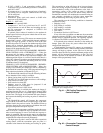
Rigging unit 3,4
Roof curb
Assembly 1
Dimensions 2
Connector package 2
Leveling tolerances 3
Weight 5
Safety considerations 1
Safety relief 45
Service 47-49
Service ports 44
Slab mount 3
Start-up 44-47
Start-up checklist CL-1
Supply-air temperature sensor 14,21
Thermostat 12, 24
Troubleshooting 49-53
Ventilation 45
Weight
Corner 6
EconoMi$er IV 5, 6
Unit 4-6
Wiring
4to20mAcontrol 20
EconoMi$er2 20
EconoMi$er IV 19
Power connections 7
PremierLink 16
Thermostat 12
Unit 51