


14
PREMIERLINK™ CONTROL — The PremierLink control-
ler is compatible with Carrier Comfort Network® (CCN)
devices. This control is designed to allow users the access and
ability to change factory-defined settings, thus expanding
the function of the standard unit control board. Carrier’s diag-
nostic standard tier display tools such as Navigator™ module
or Scrolling Marquee can be used with the PremierLink
controller.
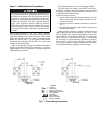
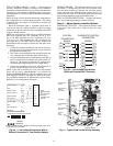
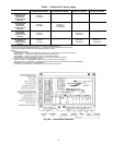
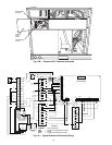
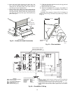
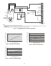
The PremierLink controller (see Fig. 15A and 15B) requires
a Carrier electronic thermostat or a CCN connection for time
broadcast to initiate its internal timeclock. This is necessary for
broadcast of time of day functions (occupied/unoccupied). Re-
fer to Fig. 16. The PremierLink control may be mounted in the
control panel or an area below the control panel.
NOTE: PremierLink versions 1.3 and later are shipped in Sen-
sor mode. If used with a thermostat, the PremierLink control
must be configured to Thermostat mode.
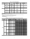
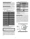
The PremierLink control includes a supply-air temperature
sensor (SAT) and an outdoor-air temperature sensor (OAT) as
standard. An indoor-air quality (CO
2
) sensor can be added as
an option. Refer to Table 5 for sensor usage.
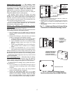
Install the Supply Air Temperature (SAT) Sensor
—When
the unit is supplied with a factory-mounted PremierLink con-
trol, the supply-air temperature (SAT) sensor (33ZCSENSAT)
is factory-supplied and wired. The wiring is routed from the
PremierLink control over the control box, through a grommet,
into the fan section, down along the back side of the fan, and
along the fan deck over to the supply-air opening.
The SAT probe is wire-tied to the supply-air opening (on the
horizontal opening end) in its shipping position. Remove the
sensor for installation. Re-position the sensor for installation.
Re-position the sensor in the flange of the supply-air opening
or in the supply air duct (as required by local codes). Drill or
punch a
1
/
2
-in. hole in the flange or duct. Use two field-
supplied, self-drilling screws to secure the sensor probe in a
horizontal orientation.
NOTE: The sensor must be mounted in the discharge airstream
downstream of the cooling coil and any heating devices. Be
sure that the probe tip does not come in contact with any of the
unit or heat surfaces.
Outdoor Air Temperature (OAT) Sensor
— When the unit is
supplied with a factory-mounted PremierLink control, the
outdoor-air temperature (OAT) sensor is factory-supplied and
wired.
Install the Indoor Air Quality (CO
2
)Sensor — Mount the
optional indoor air quality (CO
2
) sensor according to manufac-
turer specifications.
A separate field-supplied transformer must be used to pow-
er the CO
2
sensor.
Wire the CO
2
sensor to the COM and IAQI terminals of J5
on the PremierLink controller. Refer to the PremierLink Instal-
lation, Start-up, and Configuration Instructions for detailed
wiring and configuration information.
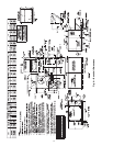
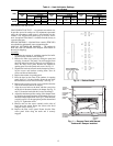
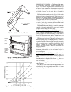
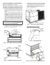
Fig. 12 — Outdoor-Air Hood Details
SCREW
HOLES
(TOP)
HOOD
HOOD
SCREEN
LOCATION
(SCREEN
NOT
SHOWN)
Fig. 13 — Optional Manual Outdoor-Air
Damper with Hood Attached
Fig. 14 — Outdoor Air Damper Position Setting