


25
CO
2
sensor to the actuator when the CO
2
concentration in the
space is at 1100 ppm. The DCV set point may be left at 2 volts
since the CO
2
sensor voltage will be ignored by the
EconoMi$er IV controller until it rises above the 3.6 volt set-
ting of the minimum position potentiometer.
Once the fully occupied damper position has been deter-
mined, set the maximum damper demand control ventilation
potentiometer to this position. Do not set to the maximum posi-
tion as this can result in over-ventilation to the space and poten-
tial high-humidity levels.
CO
2
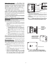
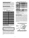
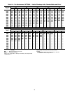
Sensor Configuration —TheCO
2
sensor has preset
standard voltage settings that can be selected anytime after the
sensor is powered up. See Table 8.
Use setting 1 or 2 for Carrier equipment. See Table 8.
1. Press Clear and Mode buttons. Hold at least 5 seconds
until the sensor enters the Edit mode.
2. Press Mode twice. The STDSET Menu will appear.
3. Use the Up/Down button to select the preset number. See
Table 8.
4. Press Enter to lock in the selection.
5. Press Mode to exit and resume normal operation.
The custom settings of the CO
2
sensor can be changed any-
time after the sensor is energized. Follow the steps below to
change the non-standard settings:
1. Press Clear and Mode buttons. Hold at least 5 seconds
until the sensor enters the Edit mode.
2. Press Mode twice. The STDSET Menu will appear.
3. Use the Up/Down button to toggle to the NONSTD menu
and press Enter.
4. Use the Up/Down button to toggle through each of the
nine variables, starting with Altitude, until the desired set-
ting is reached.
5. Press Mode to move through the variables.
6. Press Enter to lock in the selection, then press Mode to
continue to the next variable.
Dehumidification of Fresh Air with DCV Control
— Infor-
mation from ASHRAE indicates that the largest humidity load
on any zone is the fresh air introduced. For some applications,
a device such as a 62AQ energy recovery unit is added to re-
duce the moisture content of the fresh air being brought into the
building when the enthalpy is high. In most cases, the normal
heating and cooling processes are more than adequate to re-
move the humidity loads for most commercial applications.
If normal rooftop heating and cooling operation is not ade-
quate for the outdoor humidity level, an energy recovery unit
and/or a dehumidification option should be considered.
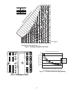
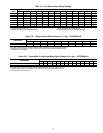
Step 7 — Adjust Indoor-Fan Speed — Adjust the
indoor-fan speed to meet jobsite conditions.
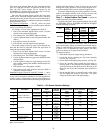
For units with electric heat, required minimum cfm is 2250
for 50TFQ008, 2550 for 50TFQ009 and 3000 for 50TFQ012
with the following exceptions:
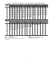
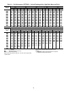
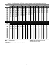
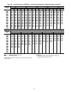
Table 9 shows indoor-fan motor data. Table 10 shows fan
rpm at motor pulley settings for standard and alternate motors.
Tables 11A and 11B show static pressure for accessories. Refer
to Tables 12-27 to determine fan speed settings. Fan motor
pulleys are factory set for speed shown in Table 1.
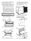
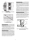
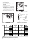
To change fan speeds:
1. Shut off the unit power supply and tag disconnect.
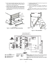
2. Loosen the belt by loosening the fan motor mounting
nuts. See Fig. 38 and 39.
3. Loosen the movable pulley flange setscrew (see Fig. 40).
4. Screw the movable flange toward the fixed flange to
increase speed or away from the fixed flange to decrease
speed. Increasing the fan speed increases the load on the
motor. Do not exceed the maximum speed specified in
Table 1.
5. Set the movable flange at nearest keyway of the pulley
hub and tighten the setscrew. (See Table 1 for speed
change for each full turn of the pulley flange.)
Table 8 — CO
2
Sensor Standard Settings
LEGEND
ppm — Parts Per Million
UNIT
UNIT
VOLTAGE
HEATER
kW
UNIT
CONFIG-
URATION
REQUIRED
MINIMUM
CFM
50TFQ012
208/230 42.4 Horizontal 3200
208/230 50.0 Horizontal 3200
460 50.0
Horizontal or
Vertical
3200
575
17.0
Horizontal or
Vertical
2800
51.0 2350
SETTING EQUIPMENT OUTPUT
VENTILATION
RATE
(cfm/Person)
ANALOG
OUTPUT
CO
2
CONTROL RANGE
(ppm)
OPTIONAL
RELAY SETPOINT
(ppm)
RELAY
HYSTERESIS
(ppm)
1
Interface w/Standard
Building Control System
Proportional Any
0-10V
4-20 mA
0-2000 1000 50
2 Proportional Any
2-10V
7-20 mA
0-2000 1000 50
3 Exponential Any
0-10V
4-20 mA
0-2000 1100 50
4
Economizer
Proportional 15
0-10V
4-20 mA
0-1100 1100 50
5 Proportional 20
0-10V
4-20 mA
0- 900 900 50
6 Exponential 15
0-10V
4-20 mA
0-1100 1100 50
7 Exponential 20
0-10V
4-20 mA
0- 900 900 50
8 Health & Safety Proportional —
0-10V
4-20 mA
0-9999 5000 500
9
Parking/Air Intakes/
Loading Docks
Proportional —
0-10V
4-20 mA
0-2000 700 50