


3
SLAB MOUNT (Horizontal Units Only) — Provide a level
concrete slab that extends a minimum of 6 in. beyond the unit
cabinet on all sides. Install a gravel apron in front of the
outdoor coil air inlet to prevent grass and foliage from obstruct-
ing airflow.
NOTE: Horizontal units may be installed on a roof curb if
required.
ALTERNATE UNIT SUPPORT — When the curb or
adapter cannot be used, support unit with sleeper rails using
unit curb or adapter support area. If sleeper rails cannot be
used, support the long sides of the unit with a minimum of
3 equally spaced 4-in. x 4-in. pads on each side.
Step 2 — Field Fabricate Ductwork — On verti-
cal discharge units, secure all ducts to the roof curb and building
structure. Do not connect ductwork to the unit. For horizontal
applications, field-supplied flanges should be attached to
horizontal discharge openings and all ductwork attached to the
flanges. Insulate and weatherproof all external ductwork, joints,
and roof openings with counter flashing and mastic in accor-
dance with applicable codes.
Ducts passing through an unconditioned space must be
insulated and covered with a vapor barrier.
If a plenum return is used on a vertical unit, the return
should be ducted through the roof deck to comply with applica-
ble fire codes.
A minimum clearance is not required around ductwork.
Cabinet return-air static pressure (a negative condition) should
not exceed 0.35 in. wg with economizer, or 0.45 in. wg without
economizer.
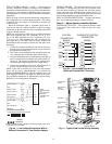
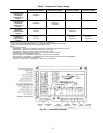
Step 3 — Install Condensate Drain Line and
External Trap —
Condensate drain connections are locat-
ed at the bottom and end of the unit. Unit discharge connec-
tions do not determine the use of drain connections;
either drain connection can be used in vertical or horizontal
applications.
When using the standard end drain connection, make sure
the plug in the alternate bottom connection is tight before in-
stalling the unit.
To use the bottom drain connection for a roof curb installa-
tion, relocate the factory-installed plug from the bottom connec-
tion to the end connection. The center drain plug looks like a star
connection, but can be removed with a
1
/
2
-in. socket drive exten-
sion. See Fig. 3. The piping for the condensate drain and external
trap can be completed after the unit is in place.
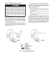
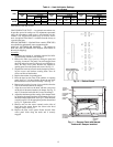
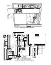
All units must have an external trap for condensate drain-
age. Install a trap at least 4-in. deep and protect against freeze-
up. If drain line is installed downstream from the external trap,
pitch the line away from the unit at
1
/
4
-in. per ft of run. Do not
use a pipe size smaller than the unit connection. See Fig. 4.
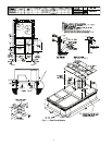
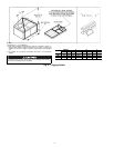
Step 4 — Rig and Place Unit — Inspect the unit for
transportation damage. File any claim with the transportation
agency. Keep the unit upright and do not drop it. Spreader bars
are not required if top crating is left on the unit. Rollers may be
used to move the unit across a roof. Level by using the unit
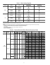
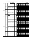
frame as a reference. See Table 1 and Fig. 5 for additional
information. Operating weight is shown in Table 1 and Fig. 5.
Lifting holes are provided in the base rails as shown in
Fig. 5 and 6. Refer to rigging instructions on the unit.
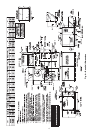
POSITIONING — Maintain clearance around and above the
unit to provide proper airflow and service access. See Fig. 6.
Position the unit on the roof curb so that the following clear-
ances are maintained:
1
/
4
-in. clearance between the roof curb
and base rails on each side and in front of the unit; 3
5
/
16
-in.
clearance between the roof curb and the outdoor fan end of the
unit (see Fig. 1, section C-C).
Do not install the unit indoors. Do not locate the unit air
inlet near exhaust vents or other sources of contaminated air.
Although the unit is weatherproof, guard against water from
higher level runoff and overhangs.
After the unit is in position, remove the polyethylene ship-
ping wrapper and rigging skid.
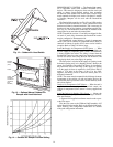
MAXIMUM ALLOWABLE
DIFFERENCE (in.)
A-B B-C A-C
0.5 1.0 1.0
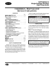
Fig. 2 — Unit Leveling Tolerances
DRAIN PLUGHORIZONTAL
DRAIN OUTLET
NOTE: Drain plug is shown in factory-installed position.
Fig. 3 — Condensate Drain Pan (Side View)
NOTE: Trap should be deep enough to offset maximum unit static
difference. A 4-in. trap is recommended.
Fig. 4 — Condensate Drain Piping Details