


12
FIELD CONTROL WIRING — Install a Carrier-approved
accessory thermostat assembly according to the installation
instructions included with the accessory. Locate the thermostat
assembly on a solid wall in the conditioned space to sense aver-
age temperature in accordance with the thermostat installation
instructions.
NOTE: If using a Carrier electronic thermostat, set the thermo-
stat configuration for “non-heat pump operation.” This family
of products does not require an O terminal to energize the
reversing valve.
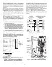
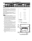
Route the thermostat cable or equivalent single leads of
colored wire from the subbase terminals to the low-voltage
connections on the unit (shown in Fig. 8A and 8B) as described
in Steps 1 through 4 below.
NOTE: For wire runs up to 50 ft, use no. 18 AWG (American
Wire Gage) insulated wire (35 C minimum). For 51 to 75 ft,
use no. 16 AWG insulated wire (35 C minimum). For over
75 ft, use no. 14 AWG insulated wire (35 C minimum). All
wire larger than no. 18 AWG cannot be directly connected to
the thermostat and will require a junction box and splice at the
thermostat.
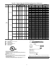
1. If the unit is mounted on the roof curb and the accessory
thru-the-curb service plate connection is used, route wire
through the connection plate.
2. Pass control wires through the hole provided on the unit
(see connection D in Connection Sizes table in Fig. 6).
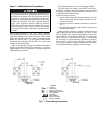
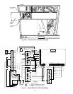
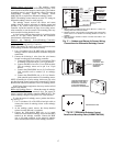
3. Feed wire through the raceway built into the corner post to
the 24-v barrier located on the left side of the control box.
See Fig. 9. The raceway provides the UL required clear-
ance between the high-voltage and low-voltage wiring.
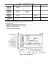
4. Connect the thermostat wires to the screw terminals of
the low-voltage connector (see Fig. 8A and 8B).
NOTE: If the unit is mounted on a roof curb and electrical
power will be run up “thru-the-bottom,” use accessory kit
number CRBTMPWR002A01. This kit, available from your
local distributor, ensures a watertight seal. Refer to the acces-
sory installation instructions for information on power wiring.
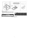
Refer to Fig. 6 for drilling holes in basepan.
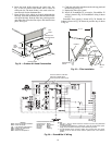
DEFROST BOARD — The defrost board timer cycle is set to
30 minutes. To change the cycle time, turn off power to the
unit and install lockout tag. Remove the wire from defrost
board connected to the 30 minute quick-connect. See Fig. 10.
Connect the wire to the 50 or 90 minute quick-connects on the
defrost board, depending on the desired defrost time.
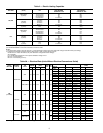
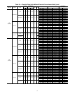
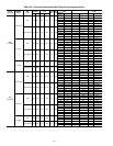
HEAT ANTICIPATOR SETTINGS — For units with electric
heat, set heat anticipator settings as shown in Table 4.
Step 6 — Adjust Factory-Installed Options
DISCONNECT SWITCH — The optional disconnect switch
is non-fused. The switch can be locked in place for safety
purposes.
WIRE
CONNECTIONS
TO
LOW-VOLTAGE
SECTION
(CONNECTION
BOARD)
COOLSTAGE 1
FAN
HEAT STAGE 1
COOLSTAGE 2
HEAT STAGE 2
24 VAC HOT
24 VAC COM
N/A
OUTDOORAIR
SENSOR
Y1/W2
G
W/W1
Y/Y2
O/W2
R
C
S1
S2
THERMOSTAT DIPSWITCH SETTINGS
R
G
Y1
Y2
W1
W2
C
IPD/X
ON
OFF
A
B
C
D
LEGEND
NOTE: Underlined letter indicates active thermostat output when
configured for A/C operation.
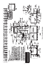
Fig. 8A — Low-Voltage Connections With or
Without Economizer or Two-Position Damper
Field Wiring
COMPRESSOR
NO. 2
DISCONNECT
BOARD
DISCONNECT
SWITCH
(OPTIONAL)
RACEWAY
HOLE IN
END
PANEL
COMPRESSOR NO. 1
CONVENIENCE
OUTLET
W2
C
Y1
G
R
Y2
W1
C
G
R
Y2
W1
X
W2
C
Y1
G
R
Y2
W1
X
24 VAC
RMTOCC
CMPSAFE
FSD
NOT USED
C
X
SFS
THERMOSTAT CONTROL
CONNECTION
BOARD
BOARD
CONNECTION
CONTROL
Fig. 9 — Typical Field Control Wiring Raceway
Fig. 8B — Low Voltage Connections
(Units with PremierLink™ Controls)