


18
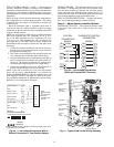
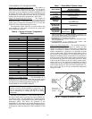
OPTIONAL ECONOMI$ER IV AND ECONOMI$ER2 —
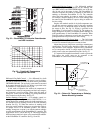
See Fig. 19 for EconoMi$er IV component locations. See
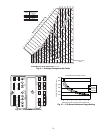
Fig. 20 for EconoMi$er2 component locations.
NOTE: These instructions are for installing the optional
EconoMi$er IV and EconoMi$er2 only. Refer to the accessory
EconoMi$er IV or EconoMi$er2 installation instructions when
field installing an EconoMi$er IV or EconoMi$er2 accessory.
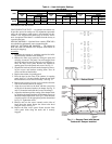
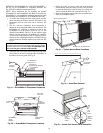
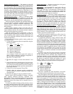
1. To remove the existing unit filter access panel, raise the
panel and swing the bottom outward. The panel is now
disengaged from the track and can be removed. See
Fig. 21.
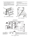
2. The box with the economizer hood components is
shipped in the compartment behind the economizer. The
EconoMi$er IV controller is mounted on top of the
EconoMi$er IV in the position shown in Fig. 19. The
optional EconoMi$er2 with 4 to 20 mA actuator signal
control does not include the EconoMi$er IV controller.
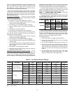
To remove the component box from its shipping position,
remove the screw holding the hood box bracket to the top
of the economizer. Slide the hood box out of the unit. See
Fig. 22.
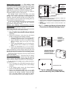
3. The indoor coil access panel will be used as the top of the
hood. Remove the screws along the sides and bottom of
the indoor coil access panel. See Fig. 23.
4. Swing out indoor coil access panel and insert the hood
sides under the panel (hood top). Use the screws provided
to attach the hood sides to the hood top. Use screws pro-
vided to attach the hood sides to the unit. See Fig. 24.
5. Remove the shipping tape holding the economizer baro-
metric relief damper in place.
IMPORTANT: If the power exhaust accessory is to be
installed on the unit, the hood shipped with the unit will not
be used and must be discarded. Save the aluminum filter
for use in the power exhaust hood assembly.
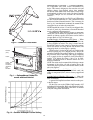
ECONOMI$ER2
PLUG
BAROMETRIC
RELIEF
DAMPER
OUTDOOR
AIR HOOD
HOOD
SHIPPING
BRACKET
GEAR DRIVEN
DAMPER
Fig. 19 — EconoMi$er IV Component Locations
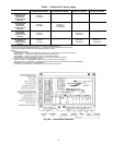
ECONOMI$ER IV
CONTROLLER
OUTSIDE AIR
TEMPERATURE SENSOR
LOW AMBIENT
SENSOR
ACTUATOR
WIRING
HARNESS
Fig. 20 — EconoMi$er2 Component Locations
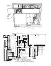
FILTER ACCESS PANEL
INDOOR COILACCESS PANEL
Fig. 21 — Typical Access Panel Locations
H
o
o
d
B
o
x
HOOD BOX
BRACKET
Fig. 22 — Hood Box Removal
SIDE
PANEL
INDOOR
COIL
ACCESS
PANEL
INDOOR
COIL
ACCESS
PANEL
CAULK
HERE
TOP
SIDE
PANEL
Fig. 23 — Indoor Coil Access Panel Relocation